Innovatory systems
The systems illustrated above have all been conventional systems in which the material is simply fed into a pipeline and either blown or sucked to its destination. Unless the material to be conveyed has natural bulk characteristics such as good air retention or permeability, however, it is unlikely that it will be possible to convey the material at low velocity, and in dense phase, in a conventional conveying system such as those described above. Even if a high pressure system is employed it is unlikely that such a material will convey in dense phase, since dense phase conveying capability is dic- tated by the properties of the material.
For materials that are either friable or abrasive, alternatives to conventional systems may have to be considered, particularly if the materials are not capable of being con- veyed in the dense phase mode, and hence at low velocities. For friable materials con- siderable particle degradation can occur in a high velocity suspension flow, and erosion of bends in the pipeline and other plant surfaces subject to particle impact will occur if an abrasive material is conveyed in dilute phase.
For a material that is only slightly hygroscopic, successful conveying may be achieved if the material is conveyed in dense phase, without the need for special air drying equipment, since air quantities required for conveying can be significantly lower than those for dilute phase. For food products, which may be subject to a loss in flavour in contact with air, dense phase conveying would automatically be recommended. If any such material is not capable of being conveyed in dense phase in conventional systems, however, alternative systems will also have to be considered.
With a need to convey many materials at low velocity, much development work has been undertaken since the late 1960s to find means of conveying materials, having no natural dense phase conveying capability, at low velocity. The innovatory systems pro- duced as a result of these developments have centred around some form of condition- ing of the conveyed material, either at the feed point into the pipeline or along the length of the pipeline. Since the modifications are essentially based on the pipeline, types of conveying system have not changed significantly.
Plug forming systems
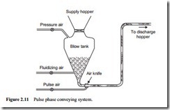
The pulse phase system was developed in the late 1960s at the Warren Spring Laboratory in the UK. It was based on the use of a bottom discharge blow tank feeding material into a pipeline. Air is supplied to the top of the blow tank to pressurize the system, to aeration rings near the bottom of the blow tank and to the air knife at the start of the conveying line. A timer switches the air to the knife on and off at a pre-determined frequency. When the air supply to the knife is on, the air pulse splits the material in the pipe-line, stops the flow of additional material from the blow tank, and pushes the severed plug a short distance along the pipeline. When the air to the knife switches off, the material again flows from the blow tank, past the air knife, and the cycle repeats itself.
No further conditioning of the material occurs along the length of the pipeline. The pulse phase system was initially developed for the handling of fine materials of a cohesive nature that are difficult to convey in conventional systems, but subsequent developments have shown that a wider range of materials can be conveyed success- fully. A typical pulse phase system is shown in Figure 2.11.
Pressure drop considerations
For materials that are impermeable and do not retain air, a short plug will completely block a pipeline, as reported in Chapter 1 (at 1.5.22). This situation corresponds to mechanically pushing a plug of material for which the pressure required varies expo- nentially with plug length, as illustrated in Figure 2.12. It is for this reason that bulk solids cannot be ‘pumped’ as a continuous plug over an appreciable distance in the same sense that a liquid can, since the pressures required are prohibitively high.
To transport bulk solids in this mode the wall friction properties must be drastically reduced and it is here that air as the motive force plays a vital role. Under such circum- stances the effect of air expanding through the interstices aerates the material so as to reduce the friction between the particles and the pipeline wall. A comparison of the pressures required to maintain movement of mechanical and aerated plugs of material in a pipeline is also shown in Figure 2.12. The exact nature of the relationship of the pressure required is not known but research suggests that it is somewhere between a linear and a square law dependence on the length of the plug, the value depending upon the properties of the material:
p rx Ln (2.1)
where p is the air pressure and L, the length of plug for 1 < n < 2.
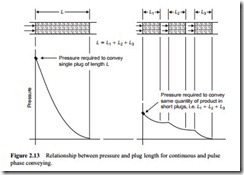
For materials that have a high value of the exponent, n, long distance conveying in this mode requires prohibitively high pressures. If the material is conveyed as a number of short plugs, separated by air gaps, then the pressure requirements can be reduced substantially. On account of the non-linear relationship between pressure and plug length, the pressure required to convey a number of short plugs is significantly less than that required to convey a single plug of equivalent length, as illustrated in Figure 2.13. By increasing the length of the air cushions, and thereby decreasing the number of plugs in the pipeline, for a given system pressure, it is possible to convey over longer distances.
By-pass systems
The most common by-pass systems employ a small pipe running inside the conveying line, having fixed ports, or flutes, at regular intervals along its length. An alternative arrangement is to have the by-pass external to the conveying pipeline and connected to it at intervals along the length. The bore of the by-pass pipe is typically 20–25 per cent of the bore of the conveying pipeline.
The spacing of the cross-connections to the external pipe, or the flutes along the length of the internal pipe, depends upon the permeability of the conveyed material. These parallel pipes are not supplied with an external supply of air, but air within the conveying line can enter freely through the regular openings provided.
The by-pass pipe may run continuously when external to the pipeline, and so include bends, but the internal fluted pipe is generally confined to straight lengths of pipeline only. A sketch of these by-pass systems is given in Figure 2.14.
Air by-pass systems are generally employed for materials that are impermeable to air and which tend to form solid plugs when conveyed at low velocity. If the material is impermeable the air will be forced to flow through the by-pass pipe if the pipeline blocks. The by-pass pipe allows air to be advanced to a point where it is capable of split- ting up the plug at the forward end and so allow conveying to continue. As the by-pass pipe is much smaller in diameter than the conveying pipeline, the air will be forced back into the pipeline through subsequent flutes, and this will effect a break-up of the plug of material causing the blockage. A long plug of material is thus divided up into short slugs that are readily conveyed.
If the bore of the by-pass pipe is one quarter of that of the conveying pipeline, for example, the pressure gradient in the by-pass pipe, with all the air flowing through it, will be 45, which is more than 1000 times greater than that in the pipeline. This means that it will not be possible for the air to by-pass the plug, but will be forced back into the pipeline through the next and subsequent flutes, and this air flow will effect a break-up of material causing the blockage [1].
Air injection systems
A number of systems have been developed that inject air into the pipeline at regular points along its length. While by-pass pipe systems artificially create permeability in the bulk material, air injection will help to maintain a degree of air retention within the material. As with the by-pass system, a parallel line runs alongside the conveying pipeline. With air injection systems, however, this parallel line is provided with an independent air supply.
The injection of additional air into the pipeline does mean, of course, that conveying air velocities towards the end of the pipeline will be increased, and such an increase in velocity will magnify problems of erosive wear and particle degradation, and could adversely affect conveying performance. Air addition, therefore, should be kept to a minimum consistent with achieving dense phase conveying in a material that would otherwise not be capable of low velocity, dense phase flow.
Air injection systems take a number of different forms. In some cases a small num- ber of injection points are situated at strategic points along a conveying line, usually after each bend and pipeline fitting. In others they are positioned at regular intervals along the length of the pipeline, spaced from less than 1 m to more than 10 m apart, depending upon the air retention properties of the material to be conveyed. In more recent developments the air is injected only at points where and when it is considered to be necessary, rather than on a continuous basis. A sketch of various air addition systems is given in Figure 2.15.
The Gattys system
A patented method that can give a material artificial air retention properties is the Gattys ‘Trace Air’ system. This was one of the first innovatory conveying systems to be
commercially available. In this system air at relatively low pressure is supplied continu- ously to the material in the pipeline through an internal perforated pipe that runs the whole length of the conveying line. The motive force comes from a pressure drop along the conveying line created by pumping air in at the upstream end, as in conventional pneumatic conveying by pipeline, but the pressures are lower and the risk of blockage is smaller [2].
Booster systems
In booster systems a separate supply of air is provided to a parallel line. Air is injected into the conveying pipeline at regular intervals along its length, typically spaced from 3 to 15 m apart, depending upon the material. In some systems sensors are positioned between the parallel airline and the conveying pipeline so that air is only injected where required. If a change in pressure difference between the two lines is detected, which would indicate that a plug is forming in the conveying pipeline, air is injected at that point to break-up the plug and so facilitate its movement.
System selection considerations
Many of the innovatory systems are capable of being stopped and re-started during operation. With most conventional systems this is not possible, and would result in considerable inconvenience in clearing pipelines, if this were necessary. In any operation where this feature would be required, therefore, one of the innovatory systems would be well worthwhile considering.
An innovatory system may also be chosen for various other reasons. Since they are capable of conveying materials in dense phase, operating costs for power are likely to be lower than those for a conventional dilute phase system. Capital costs for the innov- atory systems are almost certain to be higher, however, and so an economic assessment of the alternative systems would need to be carried out.


