We start this chapter with a discussion of view factors and the rules associated with them. View factor expressions and charts for some common configurations are given, and the crossed-strings method is presented. We then discuss radiation heat transfer, first between black surfaces and then between nonblack surfaces using the radiation network approach. We continue with radiation shields and discuss the radiation effect on temperature measurements and comfort. Finally, we consider gas radiation, and discuss the effective emissivities and absorptivities of gas bodies of various shapes. We also dis- cuss radiation exchange between the walls of combustion chambers and the high-temperature emitting and absorbing combustion gases inside.
■ THE VIEW FACTOR
Radiation heat transfer between surfaces depends on the orientation of the surfaces relative to each other as well as their radiation properties and tem- peratures, as illustrated in Fig. 22–1. For example, a camper will make the most use of a campfire on a cold night by standing as close to the fire as possible and by blocking as much of the radiation coming from the fire by turn- ing her front to the fire instead of her side. Likewise, a person will maximize the amount of solar radiation incident on him and take a sunbath by lying down on his back instead of standing up on his feet.
To account for the effects of orientation on radiation heat transfer between two surfaces, we define a new parameter called the view factor, which is a purely geometric quantity and is independent of the surface properties and temperature. It is also called the shape factor, configuration factor, and angle factor. The view factor based on the assumption that the surfaces are diffuse emitters and diffuse reflectors is called the diffuse view factor, and the view factor based on the assumption that the surfaces are diffuse emitters but specular reflectors is called the specular view factor. In this book, we will consider radiation exchange between diffuse surfaces only, and thus the term view fac- tor will simply mean diffuse view factor.
The view factor from a surface i to a surface j is denoted by and is defined as
The notation Fi ® j is instructive for beginners, since it emphasizes that the view factor is for radiation that travels from surface i to surface j. However, this notation becomes rather awkward when it has to be used many times in a problem. In such cases, it is convenient to replace it by its shorthand version Fij.
Therefore, the view factor F12 represents the fraction of radiation leaving surface 1 that strikes surface 2 directly, and F21 represents the fraction of the radiation leaving surface 2 that strikes surface 1 directly. Note that the radia- tion that strikes a surface does not need to be absorbed by that surface. Also, radiation that strikes a surface after being reflected by other surfaces is not considered in the evaluation of view factors.
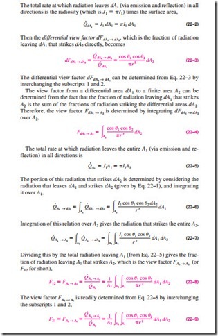
To develop a general expression for the view factor, consider two differential surfaces dA1 and dA2 on two arbitrarily oriented surfaces A1 and A2, respectively, as shown in Fig. 22–2. The distance between dA1 and dA2 is r, and the angles between the normals of the surfaces and the line that connects dA1 and dA2 are u1 and u2, respectively. Surface 1 emits and reflects radiation dif- fusely in all directions with a constant intensity of I1, and the solid angle sub- tended by dA2 when viewed by dA1 is dv21.
The rate at which radiation leaves dA1 in the direction of u1 is I1 cos u1dA1. Noting that dv21 = dA2 cos u2 /r 2, the portion of this radiation that strikes dA2 is
Note that I1 is constant but r, u1, and u2 are variables. Also, integrations can be performed in any order since the integration limits are constants. These relations confirm that the view factor between two surfaces depends on their relative orientation and the distance between them.
Combining Eqs. 22–8 and 22–9 after multiplying the former by A1 and the latter by A2 gives
which is known as the reciprocity relation for view factors. It allows the calculation of a view factor from a knowledge of the other.
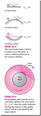
The view factor relations developed above are applicable to any two surfaces i and j provided that the surfaces are diffuse emitters and diffuse reflectors (so that the assumption of constant intensity is valid). For the special case of j = i, we have Noting that in the absence of strong electromagnetic fields radiation beams travel in straight paths, the view factor from a surface to itself will be zero unless the surface “sees” itself. Therefore, Fi ® i = 0 for plane or convex surfaces and Fi ® i * 0 for concave surfaces, as illustrated in Fig. 22–3.
The value of the view factor ranges between zero and one. The limiting case Fi ® j = 0 indicates that the two surfaces do not have a direct view of each other, and thus radiation leaving surface i cannot strike surface j directly. The other limiting case Fi ® j = 1 indicates that surface j completely surrounds sur- face i, so that the entire radiation leaving surface i is intercepted by surface j. For example, in a geometry consisting of two concentric spheres, the entire radiation leaving the surface of the smaller sphere (surface 1) will strike the larger sphere (surface 2), and thus F1 ® 2 = 1, as illustrated in Fig. 22–4.
The view factor has proven to be very useful in radiation analysis because it allows us to express the fraction of radiation leaving a surface that strikes an- other surface in terms of the orientation of these two surfaces relative to each other. The underlying assumption in this process is that the radiation a surface receives from a source is directly proportional to the angle the surface sub- tends when viewed from the source. This would be the case only if the radiation coming off the source is uniform in all directions throughout its surface and the medium between the surfaces does not absorb, emit, or scatter radiation. That is, it will be the case when the surfaces are isothermal and diffuse emitters and reflectors and the surfaces are separated by a non- participating medium such as a vacuum or air.
The view factor F1 ® 2 between two surfaces A1 and A2 can be determined in a systematic manner first by expressing the view factor between two differential areas dA1 and dA2 in terms of the spatial variables and then by performing the necessary integrations. However, this approach is not practical, since, even for simple geometries, the resulting integrations are usually very complex and difficult to perform.
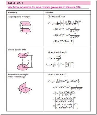
View factors for hundreds of common geometries are evaluated and the re- sults are given in analytical, graphical, and tabular form in several publica- tions. View factors for selected geometries are given in Tables 22–1 and 22–2 in analytical form and in Figs. 22–5 to 22–8 in graphical form. The view
factors in Table 22–1 are for three-dimensional geometries. The view factors in Table 22–2, on the other hand, are for geometries that are infinitely long in the direction perpendicular to the plane of the paper and are therefore two-dimensional.


