Pneumatic controllers
Closed loop control, discussed briefly earlier, requires a controller which takes a desired (set point) signal and an actual (process variable) signal, computes the error then adjusts the output to an actuator to make the actual value equal the desired value.
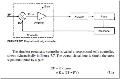
Comparison of the controller in Figure 7.7 with the force balance transmitter in Figure 7.6 shows that the differential pressure measurement (P1 – P2) performs the same function as error subtraction (SP – PV). We can thus construct a simple proportional only controller with the pneumatic circuit of Figure 7.6. Gain can be set by moving the pivot position.
The output of a proportional controller is simply K × error, so to get any output signal, an error signal must exist. This error, called the offset, is usually small, and can be decreased by using a large gain. In many applications, how- ever, too large a gain causes the system to become unstable.
In these circumstances a modification to the basic controller is used. A time integral of the error is added to give:
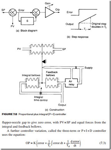
Controllers following expression 7.2 are called proportional plus integral (P + I) controllers, illustrated in Figure 7.8. The constant Ti, called the integral time, is set by the user. Often the setting is given in terms of 1/Ti (when the description repeats/min is used). A controller following expression 7.2 has a block diagram shown in Figure 7.8a, and responds to a step response as shown in Figure 7.8b. As long as an error exists, the controller output creeps up or down to a rate determined by Ti. Only when there is no error is the controller output constant. Inclusion of the integral term in expression 7.2 removes the offset error.
A pneumatic P + I controller can be constructed as shown in Figure 7.8c. Integral bellows oppose the action of the feedback bellows, with the rate of change of pressure limited by the Ti setting valve. The controller balances the correct
where Td is a user-adjustable control, called the derivative time. Addition of a derivative term makes the control output change quickly when SP or PV are changing quickly, and can also serve to make a system more stable.
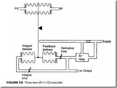
Pneumatic three-term control can be achieved with the arrangement of Figure 7.9, where the action of the feedback bellows has been delayed. The three user-adjustable terms in expression 7.3 (gain K, integral time Ti, derivative time Td) are set by beam pivot point and two bleed valves to give the best plant response. These controls do, however, interact to some extent – a failing not shared by electronic controllers.
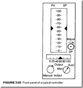
Figure 7.10 represents the typical front panel of a controller. Values of SP, PV and controller output are displayed and the operator can select between automatic and manual operation. The desired value (SP) can be adjusted in auto or the controller output set directly in manual. The operator does not have access to K, Ti, Td setting controls; these are adjusted by the maintenance technician.
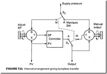
Internally the controller is arranged as shown in Figure 7.11. Setpoint and manual output controls are pressure regulators, and the auto/manual switch simply selects between the controller and manual output pressures. If the selection, however, just switched between Pc and Pm there would be a step in the controller output. The pressure regulators are designed so their output Y tracks input X, rather than the manual setting when a pressure signal is applied to B. The linked switch S2 thus makes the set point track the process variable in manual mode, while manual output Pm tracks the controller output in automatic mode. ‘Bumpless’ transfers between automatic and manual can therefore be achieved.
