Multiple delivery points
Many pneumatic conveying systems are required to deliver a material to a number of different locations. For example, by means of diverter valves in a pipeline several hoppers or silos can be loaded from a given supply point. If the delivery points are at varying distances from the supply point, however, it is unlikely that it would be possible to achieve the same material flow rate to each point. With different material flow rates, and hence solids load- ing ratios, it is possible that air flow rates would also have to be adjusted for a material capable of being conveyed in dense phase.
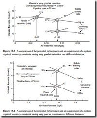
These points can be explained with reference to Figures 19.3 and 19.4. These are plots of material flow rate against air mass flow rate, and lines of constant conveying line pressure drop have been drawn for conveying distances of 100 and 200 m.
Figure 19.3 shows the situation for a material having very good air retention proper- ties and Figure 19.4 is for a material with very poor air retention properties. An air flow rate 20 per cent in excess of the minimum value required to convey each material is used for illustration purposes. Full sets of conveying characteristics for materials A and B in Figures 19.3 and 19.4 were presented in Figures 15.7–15.10.
Material influences
For materials capable of being conveyed in dense phase, an increase in conveying distance for a constant conveying line pressure drop will result in a reduction in material flow rate, and so the material will have to be conveyed at a lower solids loading ratio. At a lower value of solids loading ratio a higher minimum conveying air velocity will be
required, and hence an increase in air flow rate will be necessary. For the case shown in Figure 19.3, 0.07 kg/s of air would be needed to convey the material over 100 m as the solids loading ratio is 123; 0.135 kg/s of air would be required to convey the material over 200 m for the solids loading ratio has reduced to about 27.
This is similar to the situation presented earlier with multiple material handling and presents the same design problems. If the air supply available to the system was specified only for a distance of 100 m, at 0.07 kg/s, it would not be possible to convey the material over a distance of 200 m, even if the air supply pressure were to be reduced to compensate. If the full air flow rate of 0.135 kg/s, necessary to convey the material over 200 m, was to be used to convey the material of 100 m, however, the flow rate would be less and the power required would be very much higher than that with the correct air flow rate.
A means of controlling the air flow rate to the value appropriate to the conveying distance, therefore, needs to be incorporated in the air supply system. Controls will also be necessary on the material feed, as discussed earlier with respect to multiple material hand- ling. In the case of materials that can only be conveyed in dilute phase suspension flow no change in minimum conveying air velocity, and hence air flow rate, is necessary. There will, of course, be a change in material flow rate, as shown in Figure 19.4, and so material flow rate control will be required.
