Suction nozzles
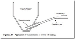
A specific application of vacuum conveying systems is the pneumatic conveying of bulk particulate materials from open storage and stockpiles, where the top surface of the material is accessible. Vacuum systems can be used most effectively for the off- loading of ships and for the transfer of materials from open piles to storage hoppers. They are particularly useful for cleaning processes such as the removal of material spillages and dust accumulations. In this role they are very similar to the domestic vacuum cleaner. For industrial applications with powdered and granular materials, however, the suction nozzles are rather more complex.
It is essential with suction nozzles to avoid filling the inlet tube solidly with material, and to maintain an adequate flow of air through the conveying line at all times. To avoid blocking the inlet pipe, sufficient air must be available at the material feed point, even if the suction nozzle is buried deep into the bulk solid material. Indeed, the vacuum off-loading system must be able to operate continuously with the nozzle buried in the material in order to maximise the material flow rate.
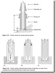
Sufficient air must also be available for conveying the material through the pipeline once it is drawn into the inlet pipe. In order to obtain maximum output through a vacuum line it is necessary to maintain as uniform a feed to the line as possible with the absolute minimum of pulsations. To satisfy these requirements two air inlets are generally required, one at the material pick-up point and another at a point downstream. A sketch of a typical suction nozzle for vacuum pick-up systems is shown in Figure 3.22.
Feed rate control
The conveying pipeline is provided with an outer sleeve at its end, and primary air for material feed is directed to the conveying line inlet in the annular space created. The length ‘a’ of this sleeve has to be long enough to ensure that it is not buried by the movement of the material and so prevent the flow of primary air. There should not be a risk of an avalanche of material from covering the air inlet at the top of the sleeve either. This sleeve may be many metres long for a ship off-loading application.
The position of the end of the sleeve relative to the end of the pipeline, ‘b’, is partly material dependent, but also has a marked influence on material flow rate. In relation to the end of the conveying pipeline, the sleeve may be retracted or extended. To a large extent this dictates the efficiency with which the material is drawn into the conveying line. This influence is illustrated in Figure 3.23 [2].
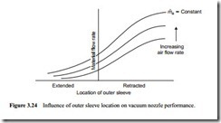
With the outer sleeve extended beyond the end of the pipeline it is more difficult for the material to be entrained in the air. If the sleeve is extended too far, the material flow rate will be zero. With the sleeve retracted behind the end of the pipeline the air readily flows into the pipeline and takes material with it. If the sleeve is retracted too far, how- ever, it becomes less effective. There is, therefore, a very narrow band of potential movement over which the vast majority of control occurs. This influence of the location of the outer sleeve on vacuum nozzle performance is illustrated in Figure 3.24. For a 50 mm bore pipeline the relative position of the outer sleeve, ‘a’, is approximately ±25 mm [2]. These parameters are, of course, material dependent to a certain extent.
From Figure 3.23b it will be seen that an element of flow rate control can also be achieved by throttling the air flow into the sleeve. This is the primary air supply and so if the end of the pipeline is starved of air a partial vacuum will be created as a conse- quence and this will have a significant effect on promoting flow. Care must be exer- cised, however, because it is very easy to over-feed the nozzle and hence block the pipeline by this means.
The use of secondary air, as illustrated with Figure 3.22 provides yet another means of controlling material flow rate. Secondary air for conveying the material is generally introduced via a series of holes in the pipeline. Some form of regulation of both the pri- mary and secondary air is necessary, and the proportion of the total air that is directed to the material inlet is particularly important. This is also material dependent, in a similar way to the proportion of the total air supply that is used in a blow tank for control of the discharge rate into the pipeline. In a way, the vacuum nozzle is very similar to a blow tank. Neither of them have any moving parts, but by proportioning the air between primary and secondary supplies, total control can be achieved over material feed rate. This is considered in more detail in Section 3.8.
Many variations in shape and design are possible, including the use of multiple ‘tails’ to a common suction line. In the case of large scale vacuum systems, such as ship off- loading, it is often necessary to attach mechanical dredging and paddle devices to the end of the nozzle. This is particularly so if materials with poor flow properties have to be unloaded, for it is essential to maintain a continuous supply of material to the nozzle to achieve the maximum potential of a vacuum line.


