Tube Cutting and Deburring
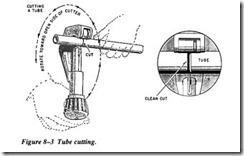
The objective of cutting tubing is to produce a square end that is free from burrs. Tubing may be cut using a standard tube cutter (Figure 8-3) or a fine-toothed hacksaw. When you use the standard tube cutter, place the tube in the cutter with the cutting
wheel at the point where the cut is to be made. Apply light pressure on the tube by tightening the adjusting knob. Too much pressure applied to the cutting wheel at one time may deform the tubing or cause excessive burrs. Rotate the cutter, adjusting the tightening knob after each complete rotation.
After the tubing is cut, remove all burrs and sharp edges from the inside and outside of the tube with a deburring tool (Figure 8-4). Clean out the tubing. Make sure no for eign particles remain.
Tube Bending
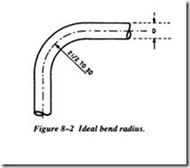
The objective in tube bending is to obtain a smooth bend without flattening the tube. Tube bending is usually done with either a hand tube bender or a mechanically oper ated bender.
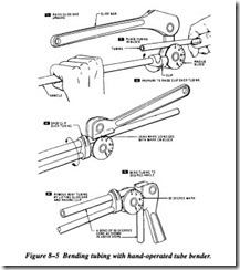
The hand tube bender (Figure 8-5) consists of a handle, a radius block, a clip, and a slide bar. The handle and slide bars are used as levers to provide the mechanical
advantage necessary to bend the tubing. The radius block is marked in degrees or bend ranging from 0 to 180 degrees. The slide bar has a mark, which is lined up with the zero mark on the radius block. The tube is inserted in the tube bender and after the marks are lined up, the slide bar is moved around until the mark on the slide bar reaches the desired degree of bend on the radius block.
Tube Flaring
Tube flaring is a method of forming the end of a tube into a funnel shape so a threaded fitting can hold it. When a flared tube is prepared, a flare nut is slipped onto the tube and the end of the tube is flared. During tube installation, the flare is seated to a fitting with the inside of the flare against the cone-shaped end of the fitting, pulling the inside of the flare against the seating surface of the fitting.
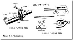
Either of two flaring tools (Figure 8-6) may be used. One gives a single flare and the other gives a double flare. The flaring tool consists of a split die block that has holes for various sizes of tubing. It also has a clamp to lock the end of the tubing inside the die block and a yoke with a compressor screw and cone that slips over the die block
and forms the 45-degree flare on the end of the tube. A double flaring tool has adapt ers that turn in the edge of the tube before a regular 45-degree double flare is made.
To use the single flaring tool, first check to see that the end of the tubing has been cut off squarely and has had the burrs removed from both the inside and outside. Slip the flare nut onto the tubing before you make the flare. Then, open the die block. Insert the end of the tubing into the hole corresponding to the OD of the tubing so that the end protrudes slightly above the top face of the die blocks. The amount by which the tubing extends above the blocks determines the finished diameter of the flare. The flare must be large enough to seat properly against the fitting, but small enough that the threads of the flare nut will slide over it. Close the die block and secure the tool with the wing nut. Use the handle of the yoke to tighten the wing nut. Then place the yoke over the end of the tubing and tighten the handle to force the cone into the end of the tubing. The completed flare should be slightly visible above the face of the die blocks.


