Hydraulic pumps and pressure regulation
A hydraulic pump (Figure 2.1) takes oil from a tank and delivers it to the rest of the hydraulic circuit. In doing so it raises oil pressure to the required level. The operation of such a pump is illustrated in Figure 2.la. On hydraulic circuit diagrams a pump is represented by the symbol of Figure 2.1b, with the arrowhead showing the direction of flow.
Hydraulic pumps are generally driven at constant speed by a three phase AC induction motor rotating at 1500 rpm in the UK (with a 50 Hz supply) and at 1200 or 1800 rpm in the USA (with a 60 Hz supply). Often pump and motor are supplied as one combined unit. As an AC motor requires some form of starter, the complete arrangement illustrated in Figure 2.1c is needed.
There are two types of pump (for fluids) or compressor (for gases) illustrated in Figure 2.2. Typical of the first type is the centrifugal pump of Figure 2.2a. Fluid is drawn into the axis of the pump, and flung out to the periphery by centrifugal force. Flow of fluid into the load maintains pressure at the pump exit. Should the pump stop, however, there is a direct route from outlet back to inlet and the pressure rapidly decays away. Fluid leakage will also occur past the vanes, so pump delivery will vary according to outlet presure. Devices such as that shown in Figure 2.2a are known as hydro dynamic pumps, and are primarily used to shift fluid from one location to another at relatively low pressures. Water pumps are a typical application.
Figure 2.2b shows a simple piston pump called a positive dis placement or hydrostatic pump. As the piston is driven down, the inlet valve opens and a volume of fluid (determined by the cross section area of the piston and the length of stroke) is drawn into the cylinder. Next, the piston is driven up with the inlet valve closed and the outlet valve open, driving the same volume of fluid to the pump outlet.
Should the pump stop, one of the two valves will always be closed, so there is no route for fluid to leak back. Exit pressure is therefore maintained (assuming there are no downstream return routes).
More important, though, is the fact that the pump delivers a fixed volume of fluid from inlet to outlet each cycle regardless of pressure at the outlet port. Unlike the hydrodynamic pump described earlier, a piston pump has no inherent maximum pressure deter mined by pump leakage: if it drives into a dead end load with no return route (as can easily occur in an inactive hydraulic system with all valves closed) the pressure rises continuously with each pump stroke until either piping or the pump itself fails.
Hydraulic pumps are invariably hydrostatic and, consequently, require some method of controlling system pressure to avoid catastrophic pipe or pump failure. This topic is discussed further in a later section.
A hydraulic pump is specified by the flow rate it delivers (usually given in litres min-1 or gallons min-1) and the maximum pressure the pump can withstand. These are normally called the pump capacity (or delivery rate) and the pressure rating.
Pump data sheets specify required drive speed (usually 1200, 1500 or 1800 rpm corresponding to the speed of a three phase induction motor). Pump capacity is directly related to drive speed; at a lower than specified speed, pump capacity is reduced and pump efficiency falls as fluid leakage (called slippage) increases. Pump capacity cannot, on the other hand, be expected to increase by increasing drive speed, as effects such as centrifugal forces, frictional forces and fluid cavitation will drastically reduce service life.
Like any mechanical device, pumps are not 100% efficient. The efficiency of a pump may be specified in two ways. First, volumetric efficiency relates actual volume delivered to the theoretical maximum volume. The simple piston pump of Figure 2.2b, for example, has a theoretical volume of Ax s delivered per stroke, but in practice the small overlap when both inlet and outlet valves are closed will reduce the volume slightly.
Second, efficiency may be specified in terms of output hydraulic power and input mechanical (at the drive shaft) or electrical (at the motor terminals) power.
Typical efficiencies for pumps range from around 90% (for cheap gear pumps) to about 98% for high quality piston pumps. An allowance for pump efficiency needs to be made when specifying pump capacity or choosing a suitable drive motor.
The motor power required to drive a pump is determined by the pump capacity and working pressure. From expression 1.6:
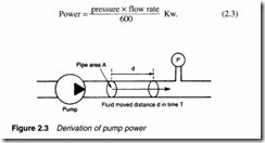
 In Figure 2.3, a pump forces fluid along a pipe of area A against a pressure P, moving fluid a distance d in time T. The force is PA, which, when substituted into expression 2.1, gives:
Unfortunately, expression 2.2 is specified in impractical SI units (pressure in pascal, time in seconds, flow in cubic metres). We may adapt the expression to use more practical units (pressure in bar, flow rate in litres min-1) with the expression:
For fully Imperial systems, motor power in horsepower can be found from:
Hydraulic pumps such as that in Figure 2.1 do not require priming because fluid flows, by gravity, into the pump inlet port. Not surprisingly this is called a self-priming pump. Care must be taken with this arrangement to avoid sediment from the tank being drawn into the pump.
The pump in Figure 2.4 is above the fluid in the tank. The pump creates a negative (less than atmospheric) pressure at its inlet port causing fluid to be pushed up the inlet pipe by atmospheric pressure. This action creates a fluid lift which is, generally, incorrectly described as arising from pump suction. In reality fluid is pushed into the pump.
Maximum pump lift is determined by atmospheric pressure and is given by expressions 1.3 and 1.4. In theory a lift of about 8 m is feasible but, in practice, would be accompanied by undesirable side effects such as cavitation (formation and destructive collapse of bubbles from partial vaporisation of fluid). The lift should be as small as possible and around 1 m is a normal practical limit.
Fluid flow in the inlet line always takes place at negative pressure, and a relatively low flow velocity is needed to reduce these side effects. The design should aim for a flow velocity of around 1 m s-1. Examination of any hydraulic system will always reveal pump inlet pipes of much larger diameters than outlet pipes.
Pressure regulation
Figure 2.5a shows the by now familiar system where a load is raised or lowered by a hydraulic cylinder. With valve V 1 open, fluid flows from the pump to the cylinder, with both pressure gauges P1 and P2 indicating a pressure of F/A. With valves V 1 closed and V2 open, the load falls with fluid being returned to the tank. With the load falling, gauge P2 will still show a pressure ofF/A, but at P1 the pump is dead-ended leading to a continual increase in pressure as the pump delivers fluid into the pipe.
Obviously some method is needed to keep P1 at a safe level. To achieve this, pressure regulating valve V3 has been included. This is normally closed (no connection between P and T) while the pres sure is below some preset level (called the cracking pressure). Once the cracking pressure is reached valve V3 starts to open, bleeding fluid back to the tank. As the pressure increases, valve V3 opens more until, at a pressure called the full flow pressure, the valve is
fully open. With valve V 1 closed, all fluid from the pump returns to the tank via the pressure regulating valve, and P1 settles somewhere between the cracking and full flow pressures.
Cracking pressure of a relief valve must be higher than a system’s working pressure, leading to a fall in system pressure as valve V 1 opens and external work is performed. Valve positions and consequent pressure readings are shown in Figure 2.5b.
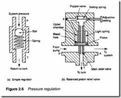
The simplest form of pressure regulation valve is the ball and spring arrangement of Figure 2.6a. System pressure in the pipe exerts a force of P x a on the ball. When the force is larger than the spring compressive force the valve will crack open, bypassing fluid back to the tank. The higher the pipe pressure, the more the valve opens. Cracking pressure is set by the spring compression and in practical valves this can be adjusted to suit the application.
The difference between cracking and full flow pressure is called the pressure override. The steady (non-working) system pressure will lie somewhere within the pressure override, with the actual value determined by pipe sizes and characteristics of the pressure regulating valve itself.
If the quiescent pressure is required to be precisely defined, a small pressure override is needed. This pressure override is related to spring tension in a simple relief valve. When a small, or precisely defined, override is required, a balanced piston relief valve (shown in Figure 2.6b) is used.
The piston in this valve is free moving, but is normally held in the lowered position by a light spring, blocking flow to the tank. Fluid is permitted to pass to the upper chamber through a small hole in the piston. The upper chamber is sealed by an adjustable spring loaded poppet. In the low pressure state, there is no flow past the poppet, so pressure on both sides of the piston are equal and spring pressure keeps the valve closed.
When fluid pressure rises, the poppet cracks and a small flow of fluid passes from the upper chamber to the tank via the hole in the piston centre. This fluid is replenished by fluid flowing through the hole in the piston. With fluid flow there is now a pressure differential across the piston, which is acting only against a light spring.
The whole piston lifts, releasing fluid around the valve stem until a balance condition is reached. Because of the light restoring spring a very small override is achieved.
The balanced piston relief valve can also be used as an unloading valve. Plug X is a vent connection and, if removed, fluid flows from the main line through the piston. As before, this causes the piston to rise and flow to be dumped to the tank. Controlled loading/unloading can be achieved by the use of a finite position valve connected to the vent connection.
When no useful work is being performed, all fluid from the pump is pressurised to a high pressure then dumped back to the tank (at atmospheric pressure) through the pressure regulating valve. This requires motor power defined earlier by expression 2.3 and 2.4, and represents a substantial waste of power. Less obviously, energy put into the fluid is converted to heat leading to a rise in fluid tempera ture. Surprisingly, motor power will be higher when no work is being done because cracking pressure is higher than working pressure.
This waste of energy is expensive, and can lead to the need for heat exchangers to be built into the tank to remove the excess heat. A much more economic arrangement uses loading/unloading valves, a topic discussed further in a later section.


