■ ANALYSIS OF HEAT EXCHANGERS
Heat exchangers are commonly used in practice, and an engineer often finds himself or herself in a position to select a heat exchanger that will achieve a specified temperature change in a fluid stream of known mass flow rate, or to predict the outlet temperatures of the hot and cold fluid streams in a specified heat exchanger.
 In upcoming sections, we will discuss the two methods used in the analysis of heat exchangers. Of these, the log mean temperature difference (or LMTD) method is best suited for the first task and the effectiveness–NTU method for the second task as just stated. But first we present some general considerations. Heat exchangers usually operate for long periods of time with no change in their operating conditions. Therefore, they can be modeled as steady-flow de- vices. As such, the mass flow rate of each fluid remains constant, and the fluid properties such as temperature and velocity at any inlet or outlet remain the same. Also, the fluid streams experience little or no change in their velocities and elevations, and thus the kinetic and potential energy changes are negligi- ble. The specific heat of a fluid, in general, changes with temperature. But, in
a specified temperature range, it can be treated as a constant at some average value with little loss in accuracy. Axial heat conduction along the tube is usually insignificant and can be considered negligible. Finally, the outer surface of the heat exchanger is assumed to be perfectly insulated, so that there is no heat loss to the surrounding medium, and any heat transfer occurs between the two fluids only.
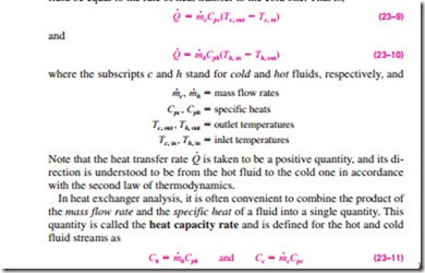
The idealizations stated above are closely approximated in practice, and they greatly simplify the analysis of a heat exchanger with little sacrifice of accuracy. Therefore, they are commonly used. Under these assumptions, the first law of thermodynamics requires that the rate of heat transfer from the hot fluid be equal to the rate of heat transfer to the cold one. That is,
The heat capacity rate of a fluid stream represents the rate of heat transfer needed to change the temperature of the fluid stream by 1°C as it flows through a heat exchanger. Note that in a heat exchanger, the fluid with a large heat capacity rate will experience a small temperature change, and the fluid with a small heat capacity rate will experience a large temperature change. Therefore, doubling the mass flow rate of a fluid while leaving everything else unchanged will halve the temperature change of that fluid.
With the definition of the heat capacity rate above, Eqs. 23–9 and 23–10 can also be expressed as
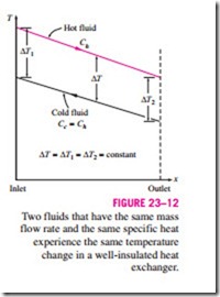
That is, the heat transfer rate in a heat exchanger is equal to the heat capacity rate of either fluid multiplied by the temperature change of that fluid. Note that the only time the temperature rise of a cold fluid is equal to the tempera- ture drop of the hot fluid is when the heat capacity rates of the two fluids are equal to each other (Fig. 23–12).
Two special types of heat exchangers commonly used in practice are con- densers and boilers. One of the fluids in a condenser or a boiler undergoes a phase-change process, and the rate of heat transfer is expressed as
where m is the rate of evaporation or condensation of the fluid and hfg is the enthalpy of vaporization of the fluid at the specified temperature or pressure.
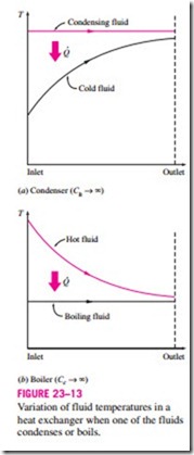
An ordinary fluid absorbs or releases a large amount of heat essentially at constant temperature during a phase-change process, as shown in Fig. 23–13. The heat capacity rate of a fluid during a phase-change process must approach infinity since the temperature change is practically zero. That is,
C = mCp → oo when /},T → 0, so that the heat transfer rate Q = mCp /},T is a finite quantity. Therefore, in heat exchanger analysis, a condensing or boiling fluid is conveniently modeled as a fluid whose heat capacity rate is infinity.
The rate of heat transfer in a heat exchanger can also be expressed in an analogous manner to Newton’s law of cooling as
where U is the overall heat transfer coefficient, As is the heat transfer area, and
/},Tm is an appropriate average temperature difference between the two fluids. Here the surface area As can be determined precisely using the dimensions of the heat exchanger. However, the overall heat transfer coefficient U and the temperature difference /},T between the hot and cold fluids, in general, are not constant and vary along the heat exchanger.
The average value of the overall heat transfer coefficient can be determined as described in the preceding section by using the average convection coefficients for each fluid. It turns out that the appropriate form of the mean tem- perature difference between the two fluids is logarithmic in nature, and its determination is presented in Section 23–4.


