Hardness measurement
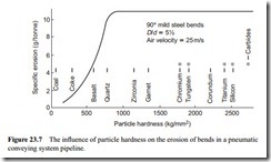
Knowledge of particle hardness is essential, therefore, particularly at the design stage of a plant, since it gives an indication of the need to take steps to avoid excessive wear of key system components. Scratch hardness is the earliest known type of hardness
test, and in its simplest form is the ability of one solid to scratch, or be scratched, by another. The method was first proposed on a semi-quantitative basis in 1822 by Mohs, who selected 10 mineral standards, starting with the softest – talc (scratch hardness 1) – and ending with the hardest – diamond (scratch hardness 10). Due to its simplicity it is still widely used today as a reference for potential erosive wear of plant by conveyed materials. This has become known as the Mohs’ hardness scale and is shown in its complete form in Table 23.1.
It should be noted that divisions along the scale are clearly not all of the same magnitude. If a Mohs’ number of a material is unknown, an indication of its value, and hence its potential abrasiveness, can be obtained by conducting a series of quick tests of the type indicated in Table 23.1. Thus cement clinker, for example, has a Mohs’ number of 6, since it can scratch any substance as hard as apatite (Mohs’ no. 5), but cannot scratch any substance as hard as quartz (Mohs’ no. 7). A convenient method of carrying out a hardness test is by the use of a set of ‘hardness pencils’. At the tip of each pencil is mounted a piece of one of the materials from the Mohs’ list. By starting with the hardest pencil, undertaking a scratch test and then repeating this with progressively less hard pencils, the Mohs’ hardness of the material can be determined.
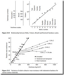
Since the Mohs’ scale proved too coarse for the measurement of the hardness of general engineering metals, quantitative tests of the static indentation type were devised, mostly based on the use of pyramids. Equipment is available for carrying out such tests with fine particulate materials, but because of its complexity, the Mohs’ scale is still used today for many bulk solids handling applications. Metal hardness, of course, is usually referred to in terms of the value indicated by one of these indentation methods. Fortunately sufficient research has been undertaken to relate the hardness as measured by any of these methods to the Mohs’ scale number. Such a relationship is shown in Figure 23.8.
Surface material
A number of surface materials were included in Figures 23.1 and 23.2. In Figure 23.2 it was shown that, for a given impact angle, the effect of velocity was similar for each
material. Figure 23.1, however, showed that impact angle could have a very different effect, with the ranking of different materials changing significantly with impact angle. From these figures it is clear that surface hardness is not necessarily the main parameter to be considered in selecting materials for erosive wear resistance.
Steels – heat treated
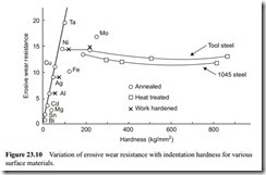
There is a wealth of information in the field of abrasive wear on the relationship between surface material hardness and wear resistance for metals. One of the earliest of these is shown in Figure 23.9 [9]. The ordinate in this case is the relative wear resistance, which
is the inverse of wear rate. This shows that the hardness value of annealed metals pro- vides an approximate estimate of their resistance to abrasive wear. Cold working fcc metals to higher hardness values has essentially no effect on abrasive wear resistance, and hardening and tempering carbon steels to achieve higher hardness levels does not result in a corresponding increase in wear resistance.
Finnie [10] was the first to show that such a relationship might exist in the field of erosive wear, but Finnie et al. [11] were the first to produce a hardness to wear resist- ance relationship similar to those presented for abrasive wear. Results of their work are presented in Figure 23.10. The range of materials that they considered was rather limited but the shape and trends of the curves were similar. Several researchers have com- mented on the possibility of micro-melting occurring over a small part of the indented surface, as mentioned in relation to Theories Proposed above at Section 23.2.1.1. This could partially over-ride the effect of heat treatment and consequent micro-structural changes.
The author has also carried out tests to determine the influence of surface hardness on erosive wear resistance [12]. An acceleration tube device was used, with silica as the abrasive material. The surface material employed was an alloy tool steel and this was hardened, and tempered over a range of temperatures, to produce a range of surface hardness values up to 830 kg/mm2. In the annealed, or ‘as received’, condition the steel had a Vickers hardness of about 230 kg/mm2.
A comparison of the two hardness extremes, with respect to impact angle, is pre- sented in Figure 23.11. This clearly shows an impact angle effect and reinforces the point that the reference conditions for any comparison with respect to erosive wear performance should always be clearly stated.
Although there is little or no difference in wear rate at very high values of impact angle, at low impact angles the heat treated material shows a significant improvement.
Pipeline is available that has been heat treated on the inner surface to high hardness values, and since straight pipeline is generally only subject to low angle glancing blows, this could offer added protection in this situation.
Resilient materials
Resilient materials, such as rubber and polyurethane, are often used in erosive wear situations. Although the hardness of the surface material is generally far lower than that of the particles impacting against the surface, they derive their erosive wear resist- ance from the fact that they are able to absorb most of the energy of impact by virtue of their resilience. Mason et al. [13] tested mild steel, nylon and Linatex (a proprietary material containing 95 per cent natural rubber) in a shot blast impact testing machine. Alumina particles were impacted at different angles over a range of velocities. They showed that the nylon and rubber exhibited typically ductile behaviour, with respect to impact angle, similar to mild steel.
Their erosive wear results, with respect to air velocity, are shown in Figure 23.12. These show that natural rubber is superior to mild steel at velocities below about 120 m/s, but above this value the performance of the rubber rapidly deteriorated. It is suspected that beyond a certain impact energy level the rubber is no longer able to absorb the energy. As a result the wear mechanism probably changes to one of tearing and possibly burning because of the heat generation. This point is considered further in Section 23.3.2.6, where the use of rubber is considered as a bend wall material.


