Pilot-operated valves
With large-capacity pneumatic valves (particularly poppet valves) and most hydraulic valves, the operating force required to move the valve can be large. If the required force is too large for a solenoid or manual operation, a two-stage process called pilot operation is used.
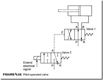
The principle is shown in Figure 4.16. Valve 1 is the main operating valve used to move a ram. The operating force required to move the valve, however, is too large for direct operation by a solenoid, so a second smaller valve 2, known as the pilot valve, has been added to allow the main valve to be operated by sys- tem pressure. Pilot pressure lines are normally shown dotted in circuit diagrams, and pilot ports on main valves are denoted Z, Y, X and so on.
Next Page
In Figure 4.16, pilot port Z is depressurized with the solenoid de-energized, and the ram is retracted. When the solenoid is energized valve 2 changes over, pressurizing Z, causing valve 1 to energize and the ram to extend.
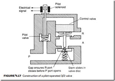
Although pilot operation can be achieved with separate valves it is more usual to use a pilot/main valve assembly manufactured as a complete ready- made unit. Figure 4.17 shows the operation of a pilot-operated 3/2 pneumatic valve. The solenoid operates the small pilot valve directly. Because this valve has a small area, a low operating force is required. The pilot valve applies line pressure to the top of the control valve, causing it to move down, closing the

