Open and closed center hydraulic circuits
A majority of the hydraulic circuits are basically categorized into two types, open center and closed center. The type of circuit is usually designated by direction control valves. In open center circuits, the pump flow is routed back to the tank through the direction control valve during neutral or dwell time. Normally in this type of circuit, a fixed displacement pump such as gear pump is used. In the event of flow being blocked during neutral or the direction control valve being centered, flow tends to get forced over the relief valve, possibly leading to the formation of an excessive amount of heat.
In the closed center circuit, the pump flow is blocked at the direction control valve both in neutral or when the valve is centered. In this case, either a pressure-compensated pump such as a piston pump that de-strokes or an unloading circuit with a fixed displacement pump is used.
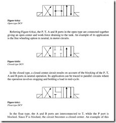
A neutral or central position is provided in a three-position direction control valve. This determines whether the circuit is open or closed and also the type of work application depending on the inter-connection between the P and T ports and the configuration of the A and B ports respectively. The four commonly used three-position direction control valves: the open type, the closed type, the tandem type and the flow type are illustrated in Figures 6.6(a)-(d).
In the tandem type, port P is connected to port T and the ports A and B are blocked. This results in an open circuit. This type finds application in circuits involving fixed volume pumps where on account of ports A and B being blocked, the load can be held in neutral.
Let us discuss some of the most commonly used direction control valves in hydraulic circuits.
Check valve
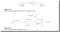
Figures 6.7(a) and (b) show the symbolic representation of a check valve along with a simple check valve application in an accumulator circuit. As the name implies, direction control valves are used to control the direction of flow in a hydraulic circuit. The simplest type is a check valve, which is a one-way direction control valve. It is a one-way valve because it permits free flow in one direction and prevents any flow in the opposite direction.
Figure 6.8 shows the internal operation of a check valve. As shown, a light spring holds the poppet in the closed position. In the free flow direction, the fluid pressure overcomes the spring force. If the flow is attempted in the opposite direction, the fluid pressure pushes the poppet (along with the spring force) in the closed position. Therefore, no flow is permitted. The higher the pressure, the greater will be the force pushing the poppet against its seat.
Pilot-operated check valve
The second type of check valve is the pilot operated check valve. The cross-section of a typical pilot operated check valve has been illustrated in Figure 6.9.
This type of check valve always enables free flow in one direction but permits flow in the normally blocked opposite direction also if the pilot pressure is applied at the pilot pressure port of the valve. The check valve poppet has a pilot piston attached to the threaded poppet stem by a nut. The light spring holds the poppet seated in a no-flow condition by pushing against the pilot piston. The purpose of the separate drain port is to prevent oil from creating a pressure build up at the bottom of the piston.
Pilot check valves are often used in hydraulic systems where it is desirable to stop the check action of the valve for a portion of the equipment cycle. An example of its application is its use in locking hydraulic cylinders in position.
Spool-type direction control valves
As discussed earlier, in spool-type direction control valves, spools incorporated in the control valve body are used to provide different flow paths. This is accomplished by the opening and closing of discrete ports by the spool lands. The spool is a cylindrical member which has large-diameter lands, machined to slide in a very close-fitting bore of the valve body. The radial clearance is usually less than 0.02 mm. The spools may be operated through different means like mechanical actuation, manual operation, pneumatic operation, hydraulic or pilot control and electrical operation.
Two-way directional valves
This type of directional valve is designed to allow flow in either direction between two ports. Figure 6.7(b) above showing a check valve application in an accumulator circuit is a typical example of a two-way, two-position on-off valve. Its function is to connect the accumulator to the load whenever desired. To put it rather simply, this valve is the hydraulic equivalent of a regular single-pole, single-throw (SPST) on-off electrical switch.
Three-way and four-way direction control valves
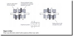
An additional type of direction control valve is the three-way and four-way valve, containing three and four ports respectively. Figure 6.10(a) depicts the flow paths through two four-way valves. As shown in the figure, one of these valves is used as a three-way valve since its port T leading to the oil tank is blocked. One of the simplest ways by which a valve port could be blocked is by screwing a threaded plug into the port opening.
Referring figure, the flow entering at pump port ‘P’ (port connected to the pump discharge line) can be directed to either of the outlet ports ‘A’ and ‘B’. Most direction control valves use a sliding spool to change the path of flow through the valve. For a given position of the spool, a unique flow path configuration exists within the valve. Directional valves are designed to operate with either two positions of the spool or three positions of the spool. Let us now analyze the flow paths through each valve shown in the figure.
Three-way valve (four-way valve used as a three-way valve)
Here the port T is blocked and only the other three ports A, B and P are used.
The flow can go through the valve in two unique ways depending on the spool position:
• Spool position 1: Flow can go from P to B as shown by the straight through line and arrow. Port A is blocked by the spool in this position.
• Spool position 2: Flow can go from P to A. Port B is blocked by the spool in this position.
Four-way valve
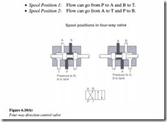
The flow can go through the valve in four unique ways depending on the spool position: Referring Figure 6.1O(b),
The pump flow can be directed to either of two different parts of a circuit by a three-way directional valve. The typical application of a four-way directional valve in hydraulic circuits involves control of double-acting hydraulic cylinders. The positioning of the direction valve spool can be done manually, mechanically, by using electrical solenoids or by using pilot pressure.
Solenoid-operated direction control valves
The most common way of actuating the spool valve is by using a solenoid. Figure 6.11 shows a typical solenoid-operated directional valve.
When the electrical coil energizes, it creates a magnetic force that pulls the armature into the coil. This causes the armature to exert a pushing force on the push rod to move the spool of the valve. Solenoids are provided at both ends of the spool. The example shown above is that of a four-way, three-position, spring-centered direction control valve.
This valve has a flow capacity of 50 lpm and a maximum operating pressure of 250 kg/cm2 (3555 psi). It has a wet armature solenoid. The fluid around the armature serves to cool it and cushion its strokes without affecting the response time. There are no seals around the armature because of which its movement is not restricted. This allows all the power developed by the solenoid to be transmitted to the spool valve without the need to overcome seal friction.
Rotary four-way direction control valves
Although most direction control valves are of spool type design, other types are also used. One such design is the rotary four-way valve, which consists of a rotor closely fitted in the valve body.
The passages in the rotor connect or block-off the ports in the valve body to provide the four flow paths. The design shown above is a three-position valve in which the centered position has all the four ports blocked. Rotary valves are usually actuated either manually or mechanically.The operation of this valve is illustrated below (Figure 6.13).
This design contains lapped metal-to-metal sealing surfaces which form a virtually leak proof seal. The gradual overlapping of the round flow passages produce a smooth shearing action which results in lesser load on the handle during operation and absence of sudden surges. Also there is no external leakage because of the presence of a static seal on the rotating shaft (non-reciprocating and non-pressurized). The high-pressure regions are confined to flow passages. This type of valve can take higher velocities and more flow than a spool valve of the same size.
These valves are available in a variety of three-way and four-way and two- and three position flow path configuration.
Shuttle valves
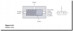
This is another type of direction control valve. It allows a system to operate from either of two fluid power sources. One application is for safety in the event that the main pump can no longer provide the hydraulic power to operate emergency devices.
As soon as the primary source is exhausted, the shuttle valve shifts to allow fluid to flow from the secondary backup pump. A typical construction of this type of valve is shown in Figure 6.14.
The shuttle valve consists of a floating piston, which can be shuttled to either side of the valve depending on which side of the piston has a greater pressure. Shuttle valves may be spring loaded in one direction to favor one of the supply sources. The shuttle valve is essentially a direct acting double check valve with a cross bleed, as depicted by the graphical symbol. The double arrows in the graphical symbol indicate that reverse flow is permitted.
