Systems with static head
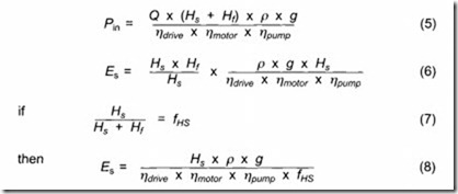
In systems with static head (H5), the energy usage can be calculated in a slightly different way. The head needed from the pump can be separated into static and dynamic (friction losses). Substituting H5+Hr for the total head in the expression for specific energy will generate the following expressions:
The “hydraulic system factor”, fHs. indicates the relative amount of static head in the system. It is obvious that Es now has a minimum value of H 8 x p x g which would occur if all efficiencies were equal to 100% (ry = 1) and there were no friction losses. If there is no variable speed drive in the system, then ‘YJdrive = 1. The different factors are all functions of the flow rate and will vary with the duty point. If a variable speed drive is used, they will vary with speed as the duty point moves along the system curve.
Motor efficiency will generally decrease as the speed is lowered and the motor goes below 75% of full load. The drop in combined motor- drive efficiency can be substantial if the motor load drops below 50% of full load. The denominator: ‘YJdrive x ‘Y/motor x ‘Y/pump x fHs can also be seen as the overall (gross) efficiency ‘Y/gr·
The hydraulic system factor will increase when the friction losses go towards zero, which happens when the duty point approaches the shut off head or when the friction losses are lowered. Hence lowering the friction losses has a substantial effect on the specific energy.
The specific energy will, however, always increase drastically as the duty point moves towards shut off head in systems with static head due to reduced pump, motor and drive efficiencies. In systems with high static head, this can happen even at a relatively moderate decrease in speed.
In such systems the area of usefulness of a variable speed drive can be somewhat improved by making sure that the system curve and the full speed pump curve intersect to the right of the pump’s best efficiency point.
To calculate the cost of pumping, the specific energy has to be calculated at all operating points along the system curve. By combining this information with the information in the flow duration diagram the cost of pumping can be determined.
