Flow regulation by varying speed
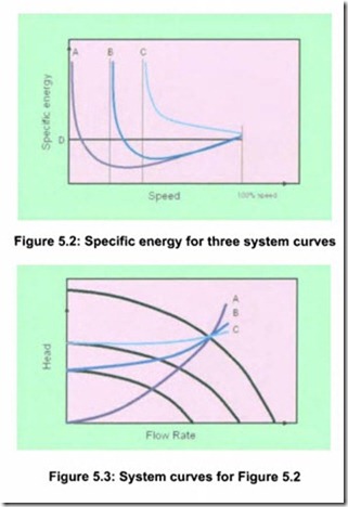
The resulting curves for specific energy as a function of speed for three different system curves are shown in Figure 5.2. Figure 5.3 shows the cor responding system curves. The intersection of the two reduced speed pump curves with the system curves B and C, indicate shut off head where the specific energy goes towards infinity. It can be seen that the savings potential is very large at low static head, curve A, whereas care has to be taken in high static head situations, represented by curve C.
When the speed is low enough to cause the pump to operate at or close to shut-off head, the specific energy always goes towards infinity. In case A, this will occur since the motor-drive efficiency will approach zero with no load.
The line D indicates the specific energy at which the pump is operating when using on-off control. When operating below this line, energy savings will be realized compared to on-off operation.
