Compressed air distribution
Mains systems
Alternatives available are a dead end main or a ring main. A dead end main has the advantage of distributing the compressed air over the shortest possible run, reducing pressure drop and economising on pipe cost. Its chief disadvantage is its lack of flexibility, although the service supplied by a compressor can be extended by the use of a split flow main, taking two separate mains from the compressor. Typical dead end mains are shown in Figure 1.
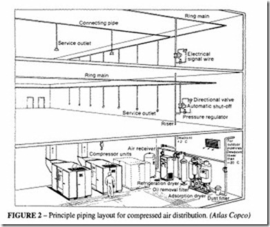
A ring main has the advantage that, being in the form of a closed circuit, the velocity of the air in the main will be reduced and the pressure drop will be less. The ring main itself may be of appreciable volume and capable of acting as a form of reservoir, to assist in maintaining pressure at any point when there is a sudden draw-off. Also, if the system is extended by the addition of a single branch, this branch can draw its supply from both ends of the main, reducing velocity and minimising pressure drop. A ring main offers maximum flexibility with functional advantages and is generally the preferred choice, but the longer length makes it essential to take care over reducing leaks. A typical layout is shown in Figure 2.
Regardless of the type of main, the most important consideration is that the pipeline shall be of suitable size to pass the maximum demand without significant pressure drop, which represents a power loss. A low pressure drop means that the operating range of the compressor can be reduced.
Mains sizing
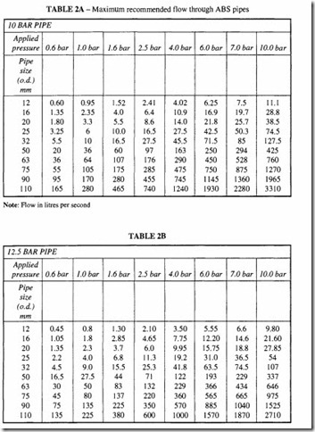
It might be thought that the ideal is to choose the largest possible pipe size, to minimize the pressure loss. Apart from the extra cost and weight of oversized pipes, they represent a volume which has to be filled by the compressor and wasted on shut down. A reasonable compromise has to be found, taking into account the acceptable pressure loss at the point of use. A variety of empirical rules have been suggested, but the most satisfactory method of establishing sizes is to calculate the flow rates throughout the system, using the data provided in the chapter on Pressure Drop Calculations.
The critical condition is when all the items of equipment are functioning simultaneously and when the correct pressure to operate them is available. In a ring main the flow will come from two directions. The pressure available at the extremes of the system will vary according to the demand. Ifa motor or tool has to generate its maximum power and needs a certain pressure to do so, that pressure may not be available if all other devices are acting simultaneously.
Most compressors are capable of generating a pressure at their delivery port greater than that required to operate standard workshop or construction equipment. Most tools give an adequate performance at 6 bar, while compressors are available with a delivery pressure of 8 to I 0 bar. A pressure drop along the distribution line of 2 bar might not be noticed by the operator, since his equipment would function satisfactorily, however such a situation would be very wasteful of energy.
Some of the empirical rules suggested for determination of pipe sizes are:
I. Limit the velocity of the air to a prescribed value. I5 m/s is suggested as a limit.
The British Compressed Air Society recommend 6 m/s to avoid carry over of moisture past the drain legs. A reasonable compromise is 6 m/s for the main lines and I5 m/s for branch lines that do not exceed I5 min length.
A criterion based on applying a velocity limitation results in an equation of the form:
2. Limit the pressure drop to the point of use to a prescribed value, eg 0.1 bar or 0.5 bar or as a proportion of the supply pressure, say 5%. This is a rather better method, since it takes into account the length of the pipe run and the pressure needed to operate the various kinds of equipment. One way of using this method is to take the pipe friction factor f from the tables in the chapter on Pipe Flow Calculations and apply the Darcy equation:
The procedure in solving for the correct pipe diameter is:
• Choose a diameter D and obtain a value of f/D from the tables.
• From the calculated maximum flow rate, determine the flow velocity, v.
• Calculate the value of M>IP. If the pressure drop is satisfactory, the chosen value ofD is correct. Otherwise select another value ofD and repeat the calculation. The valueofLis to be taken as the effective length of the pipe run, replacing all the bends and fittings by their equivalent length. This method can be tedious, but with the use of a suitable computer program, the burden of calculation can be much reduced.
One advantage of this method is that it is able to take account of the benefits of using smooth bore pipes, such as aluminium or copper, which have a lower pressure loss per unit length than the more common steel pipes.
A further method which combines the two previous methods is to limit the flow velocity to 6 m!s in the ring main and then check that the pressure drop is lower than 0.1 bar (or whatever criterion has been decided), and that the final pressure is high enough to operate the equipment. The diameter can be increased if necessary.
Basic geometry
Overhead location of an air main is the best choice, whenever this is feasible, particularly with ring mains. This enables the mains to cover the working area in a direct way. This is generally cheaper to install, minimizes the number of bends and makes maintenance easier. In the case of a dead end main there can be a case for a low level main, where each building is served by its own compressor. The main run is run at a bench height of0.45m to 0.6m, carried on floor mounted stanchions at a spacing of 3 to 4m. The airlines should be marked in accordance with BS 1710 to identify the various services and to distinguish between high and low pressure.
Mains fall
It is important that an air main shall have a fall in the direction of the airflow with moisture traps at suitable points along the run. A fall of about I in I DOor I in 120is enough to ensure that water separating out is carried along to a low point. An automatic trap is to be preferred as these cannot become overfilled and inoperative.
Branch mains or individual take-off points should emerge in the form of an upward loop. This will help to contain any condensate in the main and minimise the carry-over. A filter and separator should be fitted in the main at a high point between the compressor and first take-off point, to reduce the amount of moisture entering the main and branch lines.
Each branch and take-off point should have its own isolating stop valve and drain or drain cock at the blind end. Filters, separators and lubricators should be in the individual Jines feeding tools or appliances requiring protection and lubrication. See Figure 3 for some typical installations.
The choice of these devices will depend on the type of tool or appliance concerned.
Tools normally require a moisture separator and reducing valve in the feed line. For paint spraying, a moisture separator and reducing valve unit is required, enabling the pressure to be controlled at the take off point. Blow guns should also be used with a pressure reducing valve to control the force of the jet.
When the main involves any appreciable length of run, flange connections and expansion joints should be used throughout the system to make maintenance easier. The run should be above ground so that leaks can be identified and rectified.
Pressure drop is affected mainly by restrictions in the flow caused by changes in diameter or direction. The interior of all pipes should be smooth and clean; steel pipes should be galvanised. Sharp elbows, tees and similar fittings should be avoided in favour oflarge sweeps. All fittings should be full bore. Similar considerations apply to valves and hose connections.
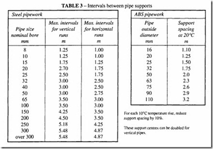
Adequate pipe support is necessary for ring mains. Table 3 can be used for support spacing.
Outdoor air lines
Outdoor air lines present special problems, notably the need to protect the outside of pipes with an anti-corrosive paint or similar treatment and the desirability of burying the lines at frost-free depth to prevent freezing of the condensate and consequent blocking of the pipes at low temperature. Underground installations can be costly, particularly as inspection wells are also necessary to gain access to condensate traps and valves.
Overground installation, with the pipes suspended on posts or supported on plinths, is generally cheaper and simpler. Quick-coupling pipes are recommended; these have some expansion/ contraction ability to counteract thermal movement and some misalignment. With overground pipes particular attention must be given to condensate separation, where there is a risk of freezing. It is also recommended that outdoor pipes shall be of welded steel construction, hot galvanised and fitted with flange joints for water traps and valves.
Leakage losses
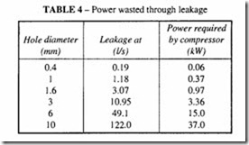
Even a small leakage hole can reduce the efficiency and waste power. Table 4 gives some examples. The entire system should be checked for leakage at regular intervals. It is commonly said that 5% of the compressor capacity should be allowed for leakage, but many systems are worse than that; anyone who has been in a empty workshop at the end of a shift will be aware of the sound of leaking air lines. The aim of the maintenance engineer should be no leakage at all. The common leakage points are hose connections, couplings and valves.
Two standard methods of determining leakage are:
1. Determine the volume V (litres) of the air main downstream of the receiver isolating valve, including all branch and drop lines. Pump up the system to normal operating pressure P1, and then shut down the compressor. Close the receiver valve and make certain that all tools and equipment are isolated. Check the time for the system to leak to a IowerpressureP2, approximately 75% ofP1. P1-P2 is the pressure drop. The leakage in litres per second of free air is given by:
2. The second method uses a compressor of known capacity as a measuring device.
This machine should be run at full load with all equipment isolated. When the system is charged to operating pressure, the compressor will unload. Due to air leaks, the air pressure will fall, causing the compressor to come on load. The duration of the period in seconds for which the compressor is on load (T) and off load (t) should be recorded at least four times.
Ifthe compressor capacity is Q Iitres/s, the air delivered is Q x T litres. The total running
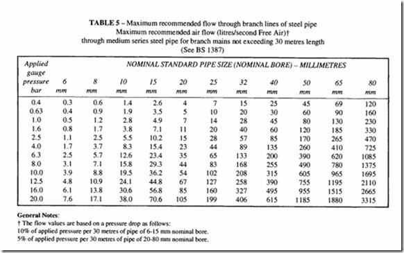
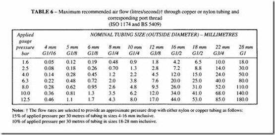
Branch lines are of relatively small diameter compared with the mains and usually supply only a single piece of equipment or a sub-system. The air consumption is usually more accurately determined than for the mains and often a higher pressure drop can be tolerated. Recommendations for sizing are given in Table 5 for steel and Table 6 for smooth bore copper or nylon. Many branch lines terminate in a flexible hose to connect to hand tools.
Refer to the chapter on Pipe Flow Calculations for advice on hose diameters. Usually when using portable tools the size of the hose connection will determine the hose size. It is not advisable to insert a reducing coupling to allow for a smaller bore hose. Heavy duty reinforced rubber hose is preferred for use on construction sites or in mines, to withstand rough treatment. Reinforced polymers may be used where there is a modest degree of
Notes: t The flow rates are selected to provide an approximate pressure drop with either nylon or copper tubing as follows: 15% of applied pressure per 30 metres of tubing in sizes 4-16 mm inclusive.
I 0% of applied pressure per 30 metres of tubing in sizes 18-28 mm inclusive.
rough treatment. For fixed and semi-fixed automation applications up to about 7 bar, un reinforced nylon may be used. For further information on choice of materials, refer to the chapter on Pipe Materials and Fittings.
Calculation of air demand for typical installations
At the planning stage of an installation it is worthwhile preparing a list of all the equipment and its likely frequency of use. This can be used to establish the maximum and likely demand and will assist in determining the correct choice of compressor and the pipe sizes. One would expect to design the installation on the basis of average consumption multiplied by a factor of 1.5, but this will vary with local circumstances. A calculation should be done on the maximum number of tools that need to be in operation simultaneously. The provision of a generously sized air receiver will assist in dealing with variable demand. If there is a large, intermittent demand at a station distant from the compressor, a further receiver close to the demand point may be worth considering. Refer to the chapter on Air Receivers for further information.

