PROCESSES AND CYCLES
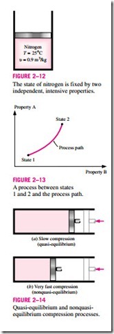
Any change that a system undergoes from one equilibrium state to another is called a process, and the series of states through which a system passes during a process is called the path of the process (Fig. 2–13). To describe a process completely, one should specify the initial and final states of the process, as well as the path it follows, and the interactions with the surroundings.
When a process proceeds in such a manner that the system remains infinitesimally close to an equilibrium state at all times, it is called a quasi-static, or quasi-equilibrium, process. A quasi-equilibrium process can be viewed as a sufficiently slow process that allows the system to adjust itself internally so that properties in one part of the system do not change any faster than those at other parts.
This is illustrated in Fig. 2–14. When a gas in a piston-cylinder device is compressed suddenly, the molecules near the face of the piston will not have enough time to escape and they will have to pile up in a small region in front of the piston, thus creating a high-pressure region there. Because of this pressure difference, the system can no longer be said to be in equilibrium, and this makes the entire process nonquasi-equilibrium. However, if the piston is moved slowly, the molecules will have sufficient time to redistribute and there will not be a molecule pileup in front of the piston. As a result, the pressure inside the cylinder will always be uniform and will rise at the same rate at all locations. Since equilibrium is maintained at all times, this is a quasi- equilibrium process.
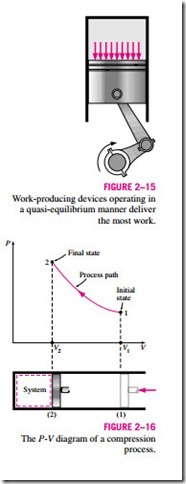
It should be pointed out that a quasi-equilibrium process is an idealized process and is not a true representation of an actual process. But many actual processes closely approximate it, and they can be modeled as quasi-equilibrium with negligible error. Engineers are interested in quasi- equilibrium processes for two reasons. First, they are easy to analyze; second, work-producing devices deliver the most work when they operate on quasi- equilibrium processes (Fig. 2–15). Therefore, quasi-equilibrium processes serve as standards to which actual processes can be compared.
Process diagrams plotted by employing thermodynamic properties as coordinates are very useful in visualizing the processes. Some common properties that are used as coordinates are temperature T, pressure P, and volume V (or specific volume v). Figure 2–16 shows the P-V diagram of a compression process of a gas.
Note that the process path indicates a series of equilibrium states through which the system passes during a process and has significance for quasi- equilibrium processes only. For nonquasi-equilibrium processes, we are not able to characterize the entire system by a single state, and thus we cannot speak of a process path for a system as a whole. A nonquasi-equilibrium process is denoted by a dashed line between the initial and final states instead of a solid line.
The prefix iso– is often used to designate a process for which a particular property remains constant. An isothermal process, for example, is a process during which the temperature T remains constant; an isobaric process is a process during which the pressure P remains constant; and an isochoric (or isometric) process is a process during which the specific volume v remains constant.
A system is said to have undergone a cycle if it returns to its initial state at the end of the process. That is, for a cycle the initial and final states are identical.
The Steady-Flow Process
The terms steady and uniform are used frequently in engineering, and thus it is important to have a clear understanding of their meanings. The term steady Work-producing devices operating in a quasi-equilibrium manner deliver the most work.
implies no change with time. The opposite of steady is unsteady, or transient. The term uniform, however, implies no change with location over a specified region. These meanings are consistent with their everyday use (steady girl- friend, uniform properties, etc.).
A large number of engineering devices operate for long periods of time un- der the same conditions, and they are classified as steady-flow devices. Processes involving such devices can be represented reasonably well by a somewhat idealized process, called the steady-flow process, which can be defined as a process during which a fluid flows through a control volume steadily (Fig. 2–17). That is, the fluid properties can change from point to point within the control volume, but at any fixed point they remain the same during the entire process. Therefore, the volume V, the mass m, and the total energy content E of the control volume remain constant during a steady-flow process (Fig. 2–18).
vices, such as reciprocating engines or compressors, do not satisfy any of the conditions stated above since the flow at the inlets and the exits will be pulsating and not steady. However, the fluid properties vary with time in a periodic manner, and the flow through these devices can still be analyzed as a steady- flow process by using time-averaged values for the properties.

