Air springs
Pneumatic cylinders as air springs
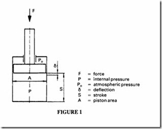
The air in a closed chamber can be used in much the same way as a metallic spring, i.e. it can be used to resist deflection by the compression of the air. The air spring has its own characteristics which differ in some important respects from the metallic spring. It can be used as an alternative to mechanical springs for suspension and for vibration isolation. The simplest form of mechanical spring is the closed pneumatic cylinder, Figure 1.
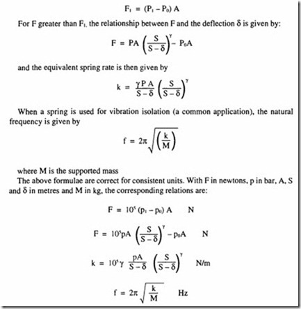
In all applications concerning air compression, the behaviour depends on the nature of the compression cycle. For very slow speed movements, the compression can be considered to be isothermal, but for high frequency suspension systems the cycle is isentropic (no heat transfer to the surroundings). The following analysis is based on an assumed isentropic cycle, with y, the index of compression equal to 1.4.
The spring of Figure 1is assumed to contain an initial air pressure, P,, which acts in the same way as a pre-load, F , in a mechanical spring. When the pre-load is taken up, the
In the above analysis, no account has been taken of seal friction, which can modify the relationships but is practically impossible to analyse. The main limitation to the use of pneumatic cylinders as vibration isolators is their reliance on elastomer seals, which are prone to wear and which cause friction. They are, however, useful for applications where a tension or a double acting spring is required.
The performance of a pneumatic spring can be modified by connecting the cylinders to a suitable external circuit as shown in Figures 2 and 3.
Gas springs are commercially available (Figure 4). These are primarily used for supporting horizontally hinged doors, but are also used for machine guards, hood supports and safety doors. They are filled with high pressure nitrogen rather than air and are heavily damped by hydraulic means. They are sealed units, factory set for the desired force characteristics, available for a maximum force up to 20 kN. For design characteristics refer to the manufacturer.
Flexible bellows
The advantages of the flexible bellows type of air spring, Figures 5 to 8, make them very versatile devices, applicable to both actuation and vibration isolation. The standard bellows has a two-ply construction of reinforced rubber with a maximum working pressure of7 bar; four-ply construction is also available with a maximum pressure of 12 bar. A maximum force of 45 kN and stroke capability of 350 mm are possible. Special formulations of rubber allow low and high temperature operation (from -50°C to 110°C).
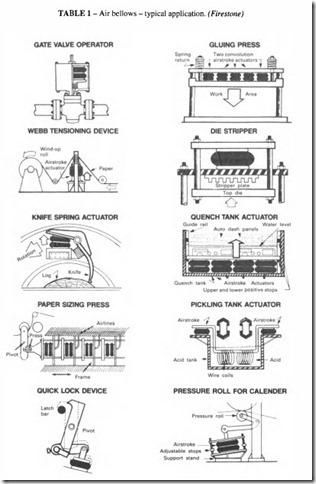
As actuators they can usefully replace conventional rams in short-stroke, high-force compression applications. Advantages include:
• no dynamic seal so no breakout friction,
• ability to stroke through an arc,
• ability to accommodate angular and side loads,
• low maintenance and generally lower cost,
• freedom from fatigue.
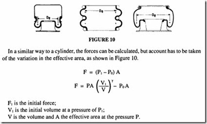
The force generated by any air spring depends on the pressure and the effective area. A cylinder has a constant area, but the effective area of a bellows changes as it extends. The force is greatest when the spring is collapsed and lessens as it extends; the variation can be as much as 50%.
As isolators, they have a substantially lower spring rate than a similarly sized rubber or
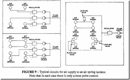
Note that in each case there is only a three point control.
reservoir is provided as in Figure 3. They eliminate problems like fatigue and permanent set fou d in other isolators. The height of air spring isolators can be accurately controlled by regulating the air pressure. With a simple feedback device, such as a levelling valve, the height can be accurately controlled to± 1em; with precision controllers, the height can be maintained to± 0.25 mm. The air supply circuit needs careful consideration. If the air is sealed in the bellows with an inflation valve, there will be some leakage through permeation over a period of time (a loss of 2 bar a year is typical), so the pressure needs to be regularly checked. Otherwise a live pressure supply must be provided either to each spring individually or to groups of springs, as shown in Figure 9. The principle to follow is that there should be only three points of control on each structure.
Design Techniques when Using Bellows
Bellows are available in a wide range of sizes and configurations. Maximum diameters vary between 150 mm and 700 mm, in the styles shown in Figures 5 to 8. Up to three convolutions are available as a single unit which can be extended by bolting several units together in series with an intermediate steel plate. Suppliers of these units provide curves which enable the static volume/height and the force/pressure relationships to be deter mined for each style. When designing an actuator system, it is better to rely on these curves than to attempt to work from basic principles.
When used as an isolator, the static curves can be used as the primary information from which to calculate the dynamic spring rate. As in the case of the cylinder discussed above, isentropic compression can be assumed (i.e. the use of an index of compression= 1.4), although a value = 1.38 is recommended by one major manufacturer; the difference is likely to be small.
The volumes and areas are obtained from the static curves.
In order to calculate the dynamic spring rate (where this value is not given in the published data), a first force at a height slightly above and a second force at a height slightly below the working height are calculated (a total height difference of25 mm can be used); the spring rate is then calculated as the force difference divided by the height difference. Using this technique, the spring rate is given by a relationship of the form:
Lis the height difference (25 mm, if that is the height difference chosen), and in this instance the suffixes I and 2 refer to values respectively above and below the working height.
The natural frequency can be calculated as before, using the calculated stiffness value.
The relationship between the forcing frequency and the natural frequency should be chosen to give the required degree of isolation, as determined from Figure II.
General consideration in the use of air springs as isolators
It is recommended that, when using the air spring as a vibration isolator, the ratio of the forced frequency to the natural frequency should be about 3:I. This will give an isolation of about 90% (see Figure II).
As the system is inherently soft, precautions must be taken to ensure stability. The ideal arrangement is to locate the springs in the same horizontal plane as the centre of gravity. Where this is not possible, the guideline to be used is: the narrowest distance between the mounting points should be at least twice the height of the centre of gravity above the plane of the springs.
The air spring should be used at the design height given in the ublished characteristics, because that height is the condition of maximum stability. Single and double convoluted springs can become unstable at a small distance away from the design height. The lateral stiffness (expressed in N/m) is oftheorderof0.2 to 0.3 times the vertical stiffness. Rolling diaphragm types on the other hand can be designed to have a high lateral stiffness equal to or greater than the vertical stiffness.
The inherent damping in an air spring is about 0.03 times critical; this is so small that for most purposes it can be neglected. Ifdamping is required, some external means has to be provided.
