Regeneration
A conventional cylinder can exert a larger force extending than retracting because of the area difference between full bore and annulus sides of the piston. The system in Figure 5.41 employs a cylinder with a full bore/annulus ratio of 2:1, and is known as a differential cylinder.
Upon cylinder extension, line pressure Pis applied to the right hand side of the piston giving a force of P x A, while the left-hand side of the piston returns oil via valve V3 against line pressure P producing a counter force P x A/2. There is thus a net force of P x A/2 to the left. When retraction is called for, a force of P x A/2 is applied to the left-hand side and fluid from the right-hand side returns to tank at minimal pressure. Extension and retraction forces are thus equal, at P x A/2.
Counterbalance and dynamic braking
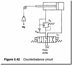
The cylinder in Figure 5.42 supports a load which can run away when being lowered. Valve V2, known as a counterbalance valve, is a pressure-relief valve set for a pressure higher than F/2 (the pressure generated in the fluid on the annulus side of the piston by the load). In the static state, valve V2 is closed and the load holds in place.
When the load is to be lowered line pressure is applied to the full bore side of the piston through valve V1. The increased pressure causes valve V2 to open and the load to lower. Check Valve V2a passes fluid to raise the load.
Counterbalance valves can also be used to brake a load with high inertia. Figure 5.43 shows a system where a cylinder moves a load with high inertia. Counterbalance valves V2 and V3 are included in the lines to both ends of the cylinder. Cross-linked pilot lines (shown dotted as per convention) keep valve V2 open when extending and valve V3 open when retracting. At constant cylinder speed, therefore, valves V2 and V3 have little effect.
To stop the load valve V1 is moved to its centre position, the pump unloads to tank and pilot pressure is lost, causing valves V2 and V3 to close. Inertia, however, maintains some cylinder move ment. If, for example, the cylinder had been extending, inertia keeps it moving to the left- raising pressure on the piston’s annulus side until valve V2 reaches its pressure setting and opens. A constant deceleration force Pa (where Pis the setting of valve V1 and a is the annulus area) is applied to the load. On deceleration, fluid passes to the full bore side of the cylinder through check valve V3a.
Pilot-operated check valves
Directional control valves and deceleration valves have a small, but definite, leakage and can only be used to hold an opposing load in position for short periods (of the order of minutes rather than hours) without the energy wasting procedure of permanently applying pressure to the cylinder.
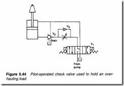
A check valve can be constructed with zero leakage. The pilot operated check valve (described in Chapter 4) can thus be used to ‘lock’ an actuator in position. Figure 5.44 shows a typical example. Valve V2 passes fluid normally when extending, but closes when valve V 1 is in its centre position. In this state, energy is saved by unloading the pump to tank. Pilot line pressure opens valve V2 when the load is to be lowered. Counterbalance valve V3 gives a controlled lowering but also ensures sufficient line pressure exists on the annulus side of the cylinder to give the pilot pressure needed to open valve V2 .
Figure 5.44 Pilot-operated check valve used to hold an over hauling load
Pre-fill and compression relief
Figure 5.45 shows the hydraulic circuit for a large press. To give the required force, a large diameter cylinder is needed and, if this is driven directly, a large capacity pump is required. The circuit shown (known as a pre-fill circuit) uses a high level tank and pilot operated check valve to reduce the required pump size.
The cross-head of the press is raised and lowered by small cylinderscl and c2. When valve vI is switched to lower, the pressure on the full bore sides of cylinders cl and c2 is low and valve v3 is closed. Valve V4 is a counterbalance valve, giving a controlled lower. As cylinders C1 and C2 extend, cylinder C3 also extends because it is mechanically coupled, drawing its fluid direct from the high level tank via pilot valve V2 .
When the cross-head contacts the load, the pressure on the full bore side of cylinders C1 and C2 rises. This causes valve V3 to open, full line pressure to be applied to cylinder C3 and check valve V2 to close. Full operating force is now applied to the load via cylinder C3.
When the cross-head is raised, pressure is applied to the annulus side of cylinders C1 and C2. This opens check valve V2, allowing fluid in cylinder c3 to be returned directly to tank.
High pressure hydraulic circuits like this require care both in design and in maintenance. For most practical purposes, hydraulic fluid can be considered incompressible. In reality, it compresses by about 0.8% per 100 bar applied pressure. When high pressure and large volumes of oil are present together, sudden release of pressure can result in an explosive release of fluid. The design must, there fore, allow for the gradual release of high pressure, high volume fluid.
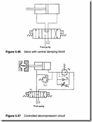
Large volume, high pressure valves are thus fitted with a central damping block as illustrated in Figure 5.46 to return fluid to tank slowly.
Figure 5.47 shows a common decompression circuit. When the cylinder extends, fluid passes to the full bore side via check valve V3 as usual, with fluid pressure rising once the load is contacted. This rise in pressure keeps valve V2 closed. When valve V 1 is returned to its centre position, the pressure decays via restriction valve RV 1. Once the pressure decays to a safe level, set by valve V2, this valve opens allowing pressure to decay fully.
Valve V4 is included to protect against a quick change from high pressure extend to retract, without a pause to allow the pressure to decay. When the full bore side of the cylinder is pressurised, valve V4 is held open causing the pump to unload to tank if retract is
requested before decompression is complete. Once pressure on the full bore side decays, valve V3 closes and the cylinder can retract as normal.
Bellows actuator
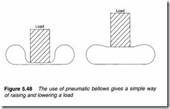
Many applications require a simple lift function, for example to raise a disappearing stop on a set of rollers. This function is usually provided by a pneumatic cylinder which requires space and mount ing lugs. A simple alternative is the bellows of Figure 5.48. In the de-energized state the bellows are deflated and the load falls under gravity. When air is passed to the bellows they inflate lifting the load. The actuator requires minimal space in its de-energized state and is simple to mount. The only disadvantage is that the load falls under gravity and is not driven down.


