mounting arrangements
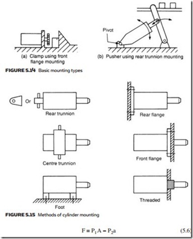
Cylinder mounting is determined by the application. Two basic types are shown in Figure 5.14. The clamp of Figure 5.14a requires a simple fixed mounting. The pusher of Figure 5.14b requires a cylinder mount which can pivot.
Figure 5.15 shows various mounting methods using these two basic types. The effects of side loads should be considered on non-centerline mountings such as the foot mount. Swivel mounting obviously requires flexible pipes.
cylinder dynamics
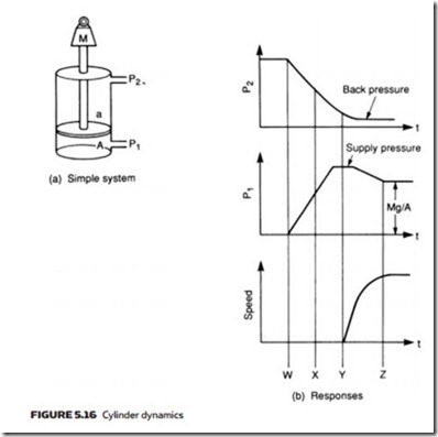
The cylinder in Figure 5.16a is used to lift a load of mass M. Assume it is retracted, and the top portion of the cylinder is pressurized. The extending force is given by the expression:
To lift the load at all, F must be greater than Mg + f where M is the mass and f the static frictional force.
The response of this simple system is shown in Figure 5.16b. At time W the rod side of the cylinder is vented and pressure is applied to the other side of the piston. The pressure on both sides of the piston changes exponentially, with falling pressure P2 changing slower than inlet pressure P1, because of the larger volume. At time X, extension force P1A is larger than P2a, but movement does not start until time Y when force, given by expression 5.6, exceeds mass and frictional force.
The load now accelerates with acceleration given by Newton’s law:
It should be remembered that Fa is not constant, because both P1 and P2 will be changing. Eventually the load will reach a steady velocity, at time Z. This velocity is determined by maximum input flow rate or maximum outlet flow rate (whichever is lowest). Outlet pressure P2 is determined by back pressure from the outlet line to tank or atmosphere, and inlet pressure is given by the expression:
The time from W to Y, before the cylinder starts to move, is called the ‘dead time’ or ‘response time’. It is determined primarily by the decay of pressure on the outlet side, and can be reduced by depressurizing the outlet side in advance or (for pneumatic systems) by the use of quick exhaust valves (described in Chapter 4).
The acceleration is determined primarily by the inlet pressure and the area of the inlet side of the piston (term P1A in expression 5.6). The area, however, interacts with the dead time – a larger area, say, gives increased acceleration but also increases cylinder volume and hence extends the time taken to vent fluid on the outlet side.
seals
Leakage from a hydraulic or pneumatic system can be a major problem, leading to loss of efficiency, increased power usage, temperature rise, environmental damage and safety hazards.
Minor internal leakage (round the piston in a double-acting cylinder, for example) can be of little consequence and may even be deliberately introduced to provide lubrication of the moving parts.
External leakage, on the other hand, is always serious. In pneumatic systems, external leakage is noisy; with hydraulic systems, external loss of oil is expensive as lost oil has to be replaced, and the resulting pools of oil are dangerous and unsightly.
Mechanical components (such as pistons and cylinders) cannot be manufactured to sufficiently tight tolerances to prevent leakage (and even if they could, the resultant friction would be unacceptably high). Seals are therefore used to prevent leakage (or allow a controlled leakage). To a large extent, the art of de- signing an actuator is really the art of choosing the right seals.
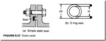
The simplest seals are ‘static seals’ (Figure 5.17) used to seal between sta- tionary parts. These are generally installed once and forgotten. A common ex- ample is the gasket shown in a typical application in Figure 5.17a. The O ring of Figure 5.17b is probably the most used static seal, and comprises a molded synthetic ring with a round cross-section when unloaded. O rings can be specified in terms of inside diameter (ID) for fitting onto shafts, or outside diameter (OD) for fitting into bores.
When installed, an O ring is compressed in one direction. Application of pressure causes the ring to be compressed at right angles, to give a positive seal against two annular surfaces and one flat surface. O rings give effective sealing at very high pressures.
O rings are primarily used as static seals because any movement will cause the seal to rotate, allowing leakage to occur.
Where a seal has to be provided between moving surfaces, a dynamic seal is required. A typical example is the end or cup seal shown, earlier, in Figure 5.9a. Pressure in the cylinder holds the lip of the seal against the barrel to give zero leakage (called a ‘positive seal’). Effectiveness of the seal increases with pressure, and leakage tends to be more of a problem at low pressures.
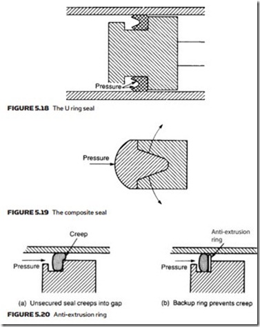
The U ring seal of Figure 5.18 works on the same principle as the cup seal. Fluid pressure forces the two lips apart to give a positive seal. Again, effective- ness of the seal is better at high pressure. Another variation on the technique is the composite seal of Figure 5.19. This is similar in construction to the U ring seal, but the space between the lips is filled by a separate ring. Application of pressure again forces the lips apart to give a positive seal.
At high pressures there is a tendency for a dynamic seal to creep into the radial gap, as shown in Figure 5.20a, leading to trapping of the seal and rapid wear. This can be avoided by the inclusion of an anti-extrusion ring behind the seal, as in Figure 5.20b.
Seals are manufactured from a variety of materials, the choice being deter- mined by the fluid, its operating pressure and the likely temperature range. The
earliest material was leather and, to a lesser extent, cork, but these have been largely superseded by plastic and synthetic rubber materials. Natural rubber cannot be used in hydraulic systems as it tends to swell and perish in the presence of oil.
The earliest synthetic seal material was neoprene, but this has a limited temperature range (below 65 °C). The most common present-day material is nitrile (buna-N), which has a wider temperature range (–50 °C to 100 °C) and is currently the cheapest seal material. Silicon has the highest temperature range (–100 °C to + 250 °C) but is expensive and tends to tear.
In pneumatic systems viton (–20 °C to 190 °C) and teflon (–80 °C to +200 °C) are the most common materials. These are more rigid and are often used as wiper or scraper seals on cylinders.
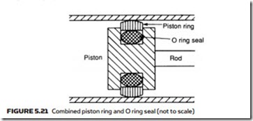
Synthetic seals cannot be used in applications where a piston passes over a port orifice which nicks the seal edges. Here metallic ring seals must be used, often with the rings sitting on O rings, as illustrated in Figure 5.21.
Seals are delicate and must be installed with care. Dirt on shafts or barrels can easily nick a seal as it is slid into place. Such damage may not be visible to the eye but can cause serious leaks. Sharp edges can cause similar damage so it is usual for shaft ends and groove edges to be chamfered.
