The air relay and the force balance principle
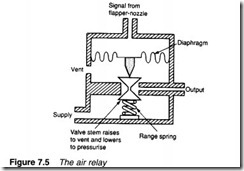
Air amplifiers balance input pressure and output pressure. An air relay, on the other hand (illustrated in Figure 7.5), balances input pressure with the force from a range spring. An increasing input signal causes air to pass from the supply to the load, while a decreasing input signal causes air to vent from the load. In the centre of the input signal range, there is no net flow to or from the output port.
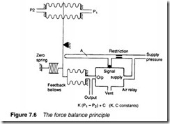
An air relay is used to linearise a flapper-nozzle, as shown in Figure 7.6. Here, force from the unbalance in input pressures P1 and P2 is matched exactly by the force from the feedback bellows whose pressure is regulated by the air relay.
Suppose flow in the pipe increases, causing pressure difference P1-P2 to increase. Increased force from the bellows at the top decreases the flapper gap causing pressure at the air relay input to
rise. This causes air to pass to the feedback bellows, which apply a force opposite to that from the signal bellows.
The system balances when the input pressure from the flapper nozzle to the air relay (point A) is at the centre of its range at which point the air relay neither passes air nor vents the feedback bellows.
This corresponds to a fixed flapper-nozzle gap.
Figure 7.6 thus illustrates an example of a feedback system where the pressure in the feedback bellows is adjusted by the air relay to maintain a constant flapper-nozzle gap. The force from the feedback bellows thus matches the force from the input signal bellows, and output pressure is directly proportional to (P1-P2). The output pressure, driven directly from the air relay, can deliver a large air volume.
The arrangement in Figure 7.6 effectively operates with a fixed flapper-nozzle gap. This overcomes the inherent non-linearity of the flapper-nozzle. It is known as the force balance principle and is the basis of most pneumatic process control devices.

