Flexible hoses
Flexible hoses are one of the most important conductors used in hydraulic systems. They are used in applications where lines must flex or bend or in other words when hydraulic components such as actuators are subjected to movement. Hoses are fabricated in layers of elastomer (synthetic rubber) and braided fabric or braided wire, which permit operation at high pressure.
Normally, hoses are rated by a safety factor between land 4. The various types of coatings and reinforcements used, determine the specific pressure ratings. The volume and velocity of the fluid flow determines the hose size and unlike pipes and tubings, hoses are designated by the inside diameter.
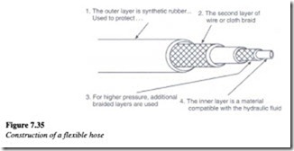
The construction of a typical flexible hose is illustrated in Figure 7.35.
The outer layer is normally made of synthetic rubber and serves to protect the braid layer. The hose can have as few as three layers (one being the braid). When multiple layers are used, they may alternate with synthetic rubber layers or the wire layers may be directly placed over one another. Hose construction has been standardized by the Society of Automotive Engineers under SAE J5-17 also known as the R series ( an example being 100 R4) by which the cover, construction, application and pressure rating is described.
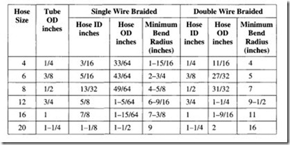
The table below gives typical hose sizes and dimensions for a single wire braided and double wire braided designs.
Size specifications of single wire braided hoses represent the outside diameter in one sixteenths of an inch of standard tubing, with the hose having the same inner diameter as that of the tubing. For example, a size 8 single wire-braided hose will have an inside diameter very close to 8116 or 1/2 in. standard tubing.
Care should be taken to change the fluid content in hoses since the hose and fluid material should be compatible. When installing the hoses, some amount of slackness is always to be ensured. This helps relieve stress. Although hoses, can last a long time, they are not as permanent as metal conductors because the rubber tends to deteriorate over a period of time due to contact with various substances such as solvents, sunlight, heat and water.
7.9.1 Hose routing and installation
The following are some of the important factors to be considered when installing a flexible hose.
Under conditions of pressure, the hose may change its length. This range in tum can be anywhere between 4 and 2%. As discussed earlier, the hose should always have some slackness during installation. This is needed to compensate for any shrinkage or expansion. However, this slackness should not be in excess as that might result in a bad installation.
If the hose is installed with a twist, high operating pressures tend to force it to straighten out. This can loosen the hose connectors and can also burst the hose at the point of
maximum strain. Therefore this condition needs to be avoided.
When the hose line passes over an exhaust manifold, or any other heat source, it must be insulated by a heat resistant boot or a metal baffle. At locations having bends, the hose length should be sufficiently long for it to form a wide radius curve. Too small a bend can pinch the hose and restrict the flow. This condition also needs to be avoided.

