■ PROPERTY DIAGRAMS INVOLVING ENTROPY
Property diagrams serve as great visual aids in the thermodynamic analysis of processes. We have used P-u and T-u diagrams extensively in previous chapters in conjunction with the first law of thermodynamics. In the second-law analysis, it is very helpful to plot the processes on diagrams for which one of the coordinates is entropy. The two diagrams commonly used in the second- law analysis are the temperature-entropy and the enthalpy-entropy diagrams. Consider the defining equation of entropy (Eq. 7–4). It can be rearranged as
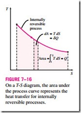
As shown in Fig. 7–16, dQrev int corresponds to a differential area on a T-S diagram. The total heat transfer during an internally reversible process is deter- mined by integration to be
which corresponds to the area under the process curve on a T-S diagram. Therefore, we conclude that the area under the process curve on a T-S diagram represents heat transfer during an internally reversible process. This is somewhat analogous to reversible boundary work being represented by the area under the process curve on a P-V diagram. Note that the area under the process curve represents heat transfer for processes that are internally (or totally) reversible. The area has no meaning for irreversible processes.
Equations 7–14 and 7–15 can also be expressed on a unit-mass basis as
To perform the integrations in Eqs. 7–15 and 7–17, one needs to know the T
relationship between T and s during a process. One special case for which these integrations can be performed easily is the internally reversible iso- thermal process. It yields
where T0 is the constant temperature and !::S is the entropy change of the sys- tem during the process.
An isentropic process on a T-s diagram is easily recognized as a vertical-
line segment. This is expected since an isentropic process involves no heat transfer, and therefore the area under the process path must be zero (Fig. 7–17). The T-s diagrams serve as valuable tools for visualizing the second-law aspects of processes and cycles, and thus they are frequently used in thermo- dynamics. The T-s diagram of water is given in the appendix in Fig. A–9.
Another diagram commonly used in engineering is the enthalpy-entropy di- agram, which is quite valuable in the analysis of steady-flow devices such as turbines, compressors, and nozzles. The coordinates of an h-s diagram repre- sent two properties of major interest: enthalpy, which is a primary property in the first-law analysis of the steady-flow devices, and entropy, which is the property that accounts for irreversibilities during adiabatic processes. In analyzing the steady flow of steam through an adiabatic turbine, for example, the vertical distance between the inlet and the exit states (!::h) is a measure of the work output of the turbine, and the horizontal distance (!::s) is a measure of the irreversibilities associated with the process (Fig. 7–18).
The h-s diagram is also called a Mollier diagram after the German scien- tist R. Mollier (1863–1935). An h-s diagram is given in the appendix for steam in Fig. A–10.


