Variables investigated
Since the conveying capacity of a pneumatic conveying system is of primary concern, major consideration has been given to material flow rate. Material properties and the effects that they have on both conveying conditions and material flow rate are particularly important. Conveying distance is clearly of fundamental importance, and pipe bore and conveying line pressure drop are both major variables that must be considered.
With this small group alone there are five independent variables, and so universal relationships are quite impossible to represent in either tabular or graphical form. Mathematical models do not exist that will adequately cover even this small group of variables or the ranges that need to be considered. In order to demonstrate the capabilities of pneumatic conveying systems, and to illustrate the influence of the major variables, therefore, several sets of curves are presented and the relationships are developed individually.
The influence of material type
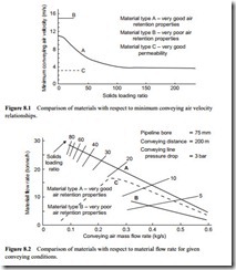
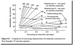
The vast differences that can exist between materials with respect to their conveying potential are illustrated in Figures 8.1 and 8.2.
For just these two plots a third material type has been added to complete the picture with regard to material types. This is material type C which covers materials that have very good permeability. To have such properties the material has to have a mean particle size above about 1 mm and for the particle size to be almost zero, so that it is effectively mono-sized. This group includes materials such as nylon and polyethylene pellets, and seeds and grains, such as peanuts. In terms of numbers of materials, this group is in a minority, compared with the other two, and so as not to confuse the issue
it is not added any further to the comparisons being made. This group of materials, however, is considered in detail in Part B of this Design Guide.
Minimum conveying air velocity
For fine powdered materials such as cement, barytes, fly ash and bentonite, that have good air retention properties, the relationship will generally be similar to that of material type A. With this group of materials a minimum conveying air velocity of about 10–12 m/s is usually sufficient to convey the material in dilute phase suspension flow. These materials are generally capable of being conveyed in dense phase, at low values of velocity, and at very high values of solids loading ratio if the pressure gradient is sufficiently high (see Figure 1.1). When conveyed at increasing solids loading ratios, these materials are generally capable of being conveyed quite successfully with air velocities very much lower than that necessary to convey the material in suspension flow.
For coarse granular materials such as sand, granulated sugar and alumina, that have poor air retention properties, the relationship will generally be similar to that of mater- ial type B. With these materials a minimum conveying air velocity of about 13–16 m/s is usually required to convey the material. These materials are not usually capable of being conveyed in any mode other than suspension flow with conventional pneumatic conveying systems. There is, therefore, little change in value of the minimum convey- ing air velocity that can be used to convey the material. Maximum values of solids loading ratio that can be achieved are generally quite low. A typical maximum value is about 15 but this can be as high as 30 if the pressure gradient is very high.
For very permeable materials conveying air velocities can also be very low, but solids loading ratios are also very low, with a typical maximum value of about 30. This is because the air flows readily through the interstices between the particles. For dilute phase conveying a minimum velocity similar to that for type B materials is required. At this point in time data on minimum conveying relationships of the type shown in Figure 8.1 can only be obtained reliably from actual conveying trials with the material. The means by which this data can be obtained is considered in Chapter 11.
Conveying air requirements
The differences in minimum conveying air velocity values that can be used for the three material types result in totally different conveying air requirements. These are shown in Figure 8.2. This is a plot of material flow rate against air mass flow rate and is drawn for a 200 m long pipeline of 75 mm bore with a pressure drop of 3 bar. With the plot being one of material flow rate against air flow rate, lines of solids loading ratio have also been added as these are simply straight lines through the origin.
Since material type A is capable of being conveyed in dense phase, conveying at a solids loading ratio of about 80 is possible with a pressure drop of 3 bar over 200 m, which agrees reasonably with Figure 1.1. With a minimum conveying air velocity of about 4 m/s, from Figure 8.1, a minimum air flow rate of about 0.08 kg/s is required. A minimum conveying air velocity of about 15 m/s is required for the type B material and so a minimum air mass flow rate of over 0.3 kg/s has to be employed. Despite the high value of conveying line pressure drop the maximum value of solids loading ratio that can be achieved with material type B is only about eight.
Conveying capabilities
In addition to the differences in air requirements for these three materials there are also differences in material flow rates that can be achieved at high air flow rates. For the materials considered here the difference is in the ratio of about 2:1. Materials A and B represent the two extremes of bulk solid materials with respect to pneumatic conveying and the majority of materials would be expected to lie between these two curves.
Major differences between materials occur because of the combined effect of the 2:1 ratio in material flow rate for a given air flow rate, and the fact that for materials that are capable of being conveyed at low velocity, the slope of the curves in the dense phase conveying region can be very different. Type C materials typically take a down- ward curve and material flow rate reduces with decrease in air flow rate. Type A materials often continue to give an increase in material flow rate with decrease in air flow rate, but many others give little or no change in material flow rate as the air flow rate is reduced. The phenomena is considered in detail in Chapters 12 and 13.
Relationships of the type shown in Figure 8.2 can only be obtained reliably from actual conveying trials with a material, in the same way as data on minimum conveying relationships mentioned above. The means by which such experimental data can be obtained is also considered in Chapter 11, with data for a number of materials being presented in subsequent chapters also.
The influence of conveying line pressure drop
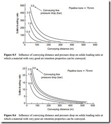
In Figure 8.2 just one constant pressure drop curve for each material was included on the plot. Figures 8.3 and 8.4 are similar plots with a range of constant pressure drop lines included. Figure 8.3 compares the two materials (A and B) when conveyed through a 50 m long pipeline of 75 mm bore, and Figure 8.4 is a similar comparison for a 500 m long pipeline. In each case the influence of conveying line pressure drop on the material conveying potential can be clearly seen.
In addition to the individual figures illustrating the influence of conveying line pressure drop on material flow rate, Figures 8.3 and 8.4 together additionally show the influence of conveying distance on material flow rate, air flow rate and solids loading ratio for the two materials. These are comprehensive conveying characteristics for a given material in a given pipeline and are the basic data for the analysis presented in this Design Guide.
The determination and use of conveying characteristics are considered in detail in Chapter 11 and in many of the following chapters in Part B of the Design Guide. The
minimum conveying conditions for a given material are defined on the conveying characteristics by relationships of the form presented in Figure 8.1.
The influence of conveying distance
Over the extremes of distance considered, the influence of conveying distance can be clearly seen by comparing Figures 8.3 and 8.4. Over the short distance of 50 m the type A material can be conveyed at extremely high values of solids loading ratios, even with low values of pressure drop. This means that the conveying limit relates to a minimum velocity of about 31⁄2 m/s over the range of pressures considered. The minimum conveying velocity for the type B material is still 15 m/s, despite the fact that there is a very high pressure gradient.
The minimum values of air flow rate required for the type B material, therefore, are more than four (15/31⁄2) times greater than those for the type A material, for any given value of pressure drop. As a consequence the minimum conveying conditions are so far apart that the conveying characteristics for the type A material can be presented in the ‘no go area’ for the type B material.
Over a distance of 500 m the pressure gradient is too low to convey the type A material in dense phase. The maximum value of solids loading ratio is less than seven and so the conveying limit now relates to a minimum conveying velocity of about 11 m/s. That for the type B material is still 15 m/s and so the two sets of conveying characteristics occupy a similar space. The significance of this is that there will have to be a significant increase in air flow rate to convey the type A material, but not for the type B material.
Solids loading ratio
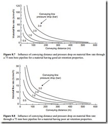
The gradual change of solids loading ratio with respect to conveying distance is shown in Figures 8.5 and 8.6.
Material flow rate
The relationship between solids loading ratio and conveying distance in Figure 8.6 is an inverse law. That in Figure 8.5 is slightly steeper because of the increase in air flow rate required by the type A material with increase in conveying distance. In Figures 8.7 and
8.8 similar plots are presented in terms of material flow rate and these are very similar.
An important point here is that if there is an increase in conveying distance there will have to be a decrease in material flow rate to compensate, unless there is an increase in energy into the system. If the air flow rate and air supply pressure remain the same, the energy input will be the same. If the air pressure is increased there will be an increase in energy and, as will be seen from any of the Figures from 8.3 to 8.7, there will be an increase in material flow rate. There will, however, have to be a slight increase in air flow
rate in addition, to compensate for the compressibility of the air, and so maintain the correct value of velocity. This particular issue is considered in Chapter 9.
An increase in air flow rate alone is unlikely to give any benefit for, as will be seen from Figures 8.3 and 8.4, the lines of constant pressure drop generally tend to have a negative slope, and certainly in the dilute phase conveying area. This means that if more air is supplied, and hence more energy to the system, less material will be conveyed. At first sight this might be difficult to comprehend but this is explained further in Chapter 11.
It must also be realized that a 75 mm bore pipeline for a conveying distance of 500 m is not likely to be a realistic option. It is used here only for illustration purposes to avoid the introduction of additional variables. The air only pressure drop has to be taken into account in every pipeline because that value of the pressure drop is not available for conveying material. If it is high little will be left to convey material. Air only pressure drop is considered in detail in Chapter 10 and is applied in subsequent chapters.
Conveying line pressure drop
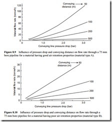
An alternative presentation of the data in Figures 8.7 and 8.8 is given in Figures 8.9 and 8.10. Conveying line pressure drop is presented on the horizontal axis and the family of curves are drawn for various conveying distances.
These two figures show that for short distance conveying a considerable increase in material flow rate can be achieved with an increase in conveying line pressure drop, and very high throughputs can be achieved with relatively small bore pipelines. If the conveying distance is very long, however, the potential of small bore pipelines is very
limited, even with high values of conveying line pressure drop. Also, if there is a limit on conveying line pressure drop, as there will be with negative pressure systems, and positive pressure systems using positive displacement blowers, the potential of small bore pipelines will be restricted automatically. In these cases consideration will have to be given to the use of larger bore pipelines.
The influence of pipeline bore
A larger bore pipeline is an obvious solution to increasing material flow rate and this clearly has much greater overall potential than air supply pressure in increasing flow rate. The potential influence of pipeline bore on the conveying performance of a pipeline is illustrated in Figures 8.11 and 8.12. These are both plots of material flow rate against pipeline bore for representative conveying conditions.
In Figure 8.11 the two materials are compared when conveyed over a distance of 200 m with a conveying line pressure drop of two bar. Figure 8.12 is a similar plot for the two materials conveyed over a distance of 100 m with a conveying line pressure drop of 1 bar.
These curves once again illustrate the differences that can exist between materials when pneumatically conveyed. They also show that quite high flow rates can be achieved with most materials, although line diameters have to be very much greater for materials having poor air retention properties. With larger bore pipelines proportionally more air is required to maintain the necessary conveying air velocities and so power will be significantly greater.
