TELETEXT RECEPTION
As suggested in Chapter 2 there are several ‘free’ TV lines in the field blanking interval of the broadcast vision signal. For many years these have been used to carry VITS (Vertical Interval Test Signals) in the form of pulse-and-bar and chroma signals: they are used for engineering tests on transmission lines and r.f. links. Other TV lines are used to convey data in the form of alphanumeric characters and graphics in coded form. A suitably equipped receiver can display pages of text and graphics, either alone or superimposed on the broadcast picture. Regularly updated magazine items such as news, travel information and share prices are transmitted, along with programme schedules, simple games, and on the commercial channels, advertisements. An invaluable service to deaf viewers is the transmission of subtitles for superimposition on the picture.
The broadcasters, terrestrial and satellite, have a standardised teletext transmission system, even though it has different on-screen names. It is possible to transmit many hundreds of pages of information on each of the networks. LSI IC techniques and the economies of scale that result from mass-production permit the data decoding function to be added quite cheaply to the basic receiver at the time of manufacture. The decoded data consists of ‘printing instructions’ for a character generator whose RGB outputs are fed to the three tube- drive amplifiers via a data-switch like that shown in the processing IC of Fig. 7.7. Each primary colour output from the decoder has only two stages – on or off – but permutations of these offer white, black, the three primaries – red, green and blue, and their complementary colours cyan, magenta and yellow.
PRINCIPLES
The teletext specification allows for the use of 16 lines per field for data transmission. The more lines used, the more information can be sent, and/or the shorter the access time for the viewer.
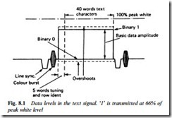
Each page of teletext contains up to 24 rows of text, each having up to 40 alphanumeric characters. The active part of the line scan is divided up into 45 equal portions each containing a pattern of eight pulses. The first five portions contain synchronising signals for the decoder; the remaining 40 designate the symbols making one line of text (Fig. 8.1). To minimise the bandwidth required, the widely used NRZ (Non-Return to Zero) system is adopted, whereby the signal voltage during a logic 1 bit period is high (66% of white level) and during logic 0 it is low at black level. The bit-rate of the data is 444 times line frequency: 6.9375 MHz.
The viewer can key in the page number required on a remote control handset. In order to enable the decoder to locate a requested page, an identification code is broadcast on the top or header row of the page being sent. Unlike the other rows, this contains only 32 displayed characters, the first eight character code groups being used for page number and control codes. Since each transmitted line of data containing the 40 characters (32 for header rows) is transmitted in sequence, it takes about 0.06 s to broadcast each page. The whole sequence of pages is recycled at regular intervals on a ‘rotating’ basis. For correct operation of the text decoder its internal clock must be locked to received bit-rate at 6.9375 MHz. At the beginning of each line the first two words are used to provide a clock ‘run-in’ for synchronisation purposes – not unlike the way in which the colour burst synchronises the reference oscillator in a chroma decoder. Once the clock has been synchronised the start of the data word must be located. Thus the next piece of data needed is the framing code which corresponds to 11100100 (Fig. 8.2) without which the decoder can- not locate the start of a line of text. The framing code is chosen so that even if (due to interference or other corruption) one bit were missing, this line of text could still be detected. Normally a shift
register, a sort of electronic queue, is used for framing code identification. As each new bit arrives it pushes its predecessor one place forward in the register, which has a capacity of eight bits. When all eight have been received the first bit arrives at the output, when the entire framing code should be present in the register. The next data word starts to enter the register, and it is possible that sometimes the bits used in this may match the framing code. During the first eight clock cycles a maximum of five bits should match the prescribed framing code. On the ninth and subsequent clock periods, provided the shift register contains at least six matching bits, the code can be detected.
Each pair of bits is examined and if they match the code the condition is termed true; if one or more is incorrect it is termed error.
Page memory
The heart of the decoder is the memory unit in which the selected page is stored to be read out as the screen display. It consists of a RAM (Random Access Memory), a large array of cells, rather like bistables, which can have two states and can be set to be either high or low, corresponding to 0 and 1. This unit needs about 7000 cells for each page it stores.
Character generator
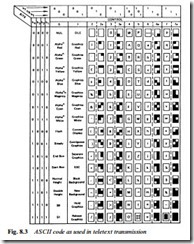
The required page of data must be converted into a display of rows of characters. These are produced by generating a pattern of dots in each character space on the screen. Another memory system is used, called ROM (Read-Only Memory). During manufacture this is pre- programmed with the required picture-element information for a whole range of alphanumerical characters as well as ‘building- blocks’ for graphics displays like maps and diagrams. Each of these has its own input code, the key to which is given in Fig. 8.3. As shown there, data is transmitted not only for the characters, but also for
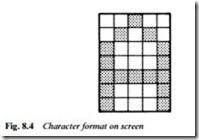
characteristics like colour, boxed, flashing, concealed and double height. Fig. 8.4 shows the formation of the letter A in a 5 × 7 dot matrix. To avoid the ‘coarseness’ at the top of this and similar letters character generator chips incorporate character rounding, in which half-elements are added in the corners and angles to give a smoother outline.
Data corruption
Very short term reflections in the path of the received broadcast picture due to ringing and ghosting may not noticeably affect reproduction of ordinary pictures, but can severely upset teletext
reproduction. The standard of receiver alignment, accuracy of tuning and integrity of the aerial and its feeder becomes important if error-free displays are to be consistently reproduced. Since teletext uses a digital mode, the strength and S/N ratio of the signal is less important than for analogue applications – perfect text is receivable down to r.f. input levels of 200 μV, when TV pictures have deteriorated to an almost unwatchable point of snow and grain.
Within the active line period depicted in Figs 8.1 and 8.2, the actual waveform shape is rounded and not a true squarewave at all. Having passed through the various transmission links and the receiver, some of the data at the input to the decoder will be below the specified 66% of peak white. Within the constraints of the transmission system, the ideal representation of a pulse train is as shown in Fig. 8.5. By taking two complementary test lines, i.e. one carrying 0101001 and the other 1010110, and displaying them on an oscilloscope, either superimposed or as a Lissajous figure with ‘scope X’ deflection operating from the teletext reference clock, the degree of distortion present can be directly viewed. The shape of the waveform produced is rather like an eye with a continuously moving thick outline. The upper ellipse represents all the ‘1’ signals and the lower ellipse all the ‘0’ signals. The distance between them is termed eyeheight, and the clear area therein (between the lowest ‘1’ and the highest ‘0’) is termed ‘worst eyeheight’ and represents the margin within which the decoder must differentiate between logic levels 0 and 1 in the received signal.


