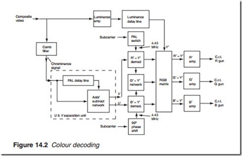
Colour decoding
As stated earlier, the chrominance information forms part of the compos- ite video, from which it has to be separated before demodulation. The chrominance information is centred on a 4.43-MHz sub-carrier with a
bandwidth limited to +l MHz. The first task of the chrominance decoder is therefore to separate the chrominance from the composite video which is carried out by a comb filter (Figure 14.2). The next task is to break up the composite chrominance signal into its two component parts, U and V, each of which must be demodulated separately to obtain the original colour difference signals. The weighted colour difference signals, U and V, are separated from each other by a unit consisting of a delay line (usually known as PAL delay line) and an add/subtract network. Two separate signals, U and V, are produced, which are fed to their respective demodu- lators, B’- Y’ and R’- Y’. Each demodulator is fed with a 4.43-MHz signal at the correct phase from the reference oscillator and burst channel. Two gamma-corrected colour difference signals, B’- Y’ and R’- Y’, are thus obtained. The third colour difference signal, G’- Y’, is obtained from the first two by the G’- Y’ network as shown. The three colour difference signals, together with luminance signal Y’, are then fed into the RGB matrix. By adding Y’ to the three colour difference signals, the original gamma-corrected R’, G’ and B’ colours are reproduced, and after amplifi- cation they are fed directly into the appropriate CRT gun. As a conse- quence of the colour decoding process, the chrominance component suffers a delay with respect to the luminance part. A luminance delay line is therefore inserted into the luminance signal path to ensure that both sig- nals arrive at the matrix at the same time.
The chrominance channel must also provide a facility for some or all of the following functions:
● Colour kill to turn the chrominance amplifier off during monochrome- only transmission.
Television receivers: colour processing 255
● Manual saturation (or colour) control to allow the user to change the colour intensity of the display by varying the gain of the chrominance amplifier.
● Automatic colour control, a.c.c. to vary the gain of the chrominance amplifier.
● Burst blanking to turn the amplifier off during the sub-carrier burst.
Failure to do this will result in a greenish striation appearing on the left side of the screen.
● Inter-carrier sound rejection. The 6 MHz sound inter-carrier must be removed by one or more 6 MHz traps in the amplifying stage.
● d.c. clamping to reintroduce the d.c. level lost during the processing channel.
It is necessary to d.c. clamp all three colour signals to ensure a common black level for the red, green and blue guns. Any drift in the d.c. level of one amplifier with respect to any of the other two would lead to overem- phasis producing an unwanted colour tint. Where a.c. coupling is used throughout the channel, d.c. clamping is carried out at the RGB drive amplifier stage. However, in modern receivers, d.c. coupling is employed for the early part of the processing system.
