CONVERGENCE
In setting up the purity, provision is made to reserve each phosphor for its own beam, but this does not mean that the patterns produced by the three beam/phosphor combinations will exactly overlay each other, an essential requirement when a composite picture is to be formed from three superimposed colour pictures. Any lack of registration will give rise to colour fringing on edges and outlines of picture features. In most colour tubes the green cathode is central in the gun and the green beam travels down the centre of the tube neck to trace out a square, central picture on the screen. Because the outer beams, red and blue, take a different path and angle through the deflection system their patterns suffer from deflection distortion preventing either from overlaying the green pattern. Steps must be taken to exactly register the three images on screen: they take two forms, static convergence and dynamic convergence.
Static convergence
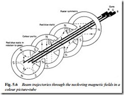
Although the dimensional and alignment tolerances in electron-gun manufacture are very tight, it is not possible to fabricate and fix the gun accurately enough to ensure that the centres of their on-screen images coincide. Centre-screen registration is called static convergence, and depends on the position of each beam-path within the tube neck. To correctly align these, a series of ring-magnet pairs is fitted on the tube neck forward of the purity rings already described. Their magnetic fields are carefully tailored to cross the paths of the outer (red and blue) electron beams while having no effect (in fact, no magnetic field) on the axis of the tube neck where passes the central green beam’s path. By means of a pair of four- pole magnets whose field intensity and direction can be varied by co- and contra-adjustment, the outer beams’ paths are moved horizontally and vertically so that their images coincide at screen centre to give a magenta (red plus blue) spot there. The position of this magenta spot will not necessarily coincide with that of the green spot, so a further ring-magnet pair, this time with six-pole field, is fitted to the tube neck.
The six-pole magnetic field set up by this third ring pair is again adjustable as to strength and direction, and because its flux patterns appear identical to the outer beams they are together moved in either a horizontal or a vertical plane so that the magenta and green images can be superimposed. Fig. 5.6 shows a typical neck magnet cluster with the effect of each ring-magnet pair on the paths of the beams. In some tube designs these neck magnet systems are not used. The required magnetic fields for tolerance correction in terms of purity and static convergence are permanently ‘printed’ into a single ring at the top of the gun assembly during the manufacturing process.
Dynamic convergence
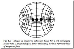
Unfortunately the achievement of perfect convergence at screen centre will not alone ensure that the registration holds correct right out to the screen edges. As the beams are deflected away from screen centre the fact that the screen is flat rather than spherical means that the deflection-centre-to-screen path becomes longer. The beams converge at the image plane, an imaginary sphere centred on the deflection centre, and diverge beyond it to strike the screen at widely different points. A solution to this problem is to take advantage of the slightly different paths of the beams through the deflection centre, and carefully shape the latter’s magnetic field to impart a corrective factor to the deflection force applied to individual beams. By very precise control of the physical position of each turn of wire in the line and field deflection coils, the shape of the flux-field each generates in the tube neck can be controlled. For a self-converging tube the vertical lines of
force responsible for horizontal deflection need to conform to a pincushion shape, and the horizontal lines of force which deflect the beams vertically to a barrel shape, as shown in Fig. 5.7.
These magnetic field patterns depend entirely on the physical shape and arrangement of the saddle-wound deflection yoke and the configuration and shape of the winding. In some designs manufacturing tolerances of tube and yoke are not sufficiently good to ensure perfect convergence at the extreme edges and corners of the picture. To take up these tolerances the front (flared) end of the deflection coil is made larger than the tube bulb flare, permitting the front of the yoke to be panned and tilted for optimum screen-edge convergence. When it is achieved the yoke is wedged and sealed in position. In a tube with green gun central, horizontal panning of the yoke has the effect of registering red and blue lines parallel to and adjacent to the screen edges, while vertical tilting of the yoke registers the extremities of the red and blue lines which pass through screen centre. In some deflection systems a four-pole electromagnet is fitted to further assist with dynamic convergence. It carries sawtooth and parabola waveforms at line and field rate, whose amplitude and shape are adjustable by six or so resistive or inductive trimmers. Differential adjustment of the currents flowing in the two halves of each deflection coil pair (scan balance controls) may also be provided to correct crossover of red and blue horizontals on the screen centre-line.

