Transport demultiplexing and MPEG decoding
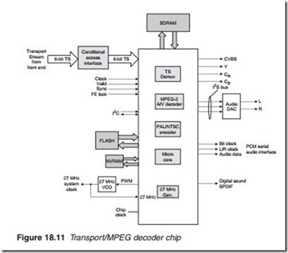
The channel decoder is followed by the transport stream demultiplexing/ video/audio MPEG-2 decoding IC package (Figure 18.11).
The input to the chip is an 8-bit wide transport stream obtained from the front end consisting of video, audio or other service information belonging to four, five or more different programmes organised into 188-byte transport
packets. The transport stream is examined to ascertain if conditional access scrambling is employed. If it is not, the CAM is bypassed and the transport stream is processed in the normal way. If the programme is encrypted, the CAM ascertains whether the user has access rights to the programme. If so, the transport stream is de-encrypted and returned to the demux for further processing. If the user has no entitlement to view the programme, the trans- port stream is blocked, giving a blank display on the screen with a message to inform the user of the problem.
The central task of the demux is to extract the transport packets that belong to the selected programme. To do this, the demux first extracts the packet with a packet identification (PID) of zero. This contains the pro- gramme association table (PAT) in which the demux will find the PID of the packet that contains the programme map table (PMT). Once the PMT is opened, the demux is able to identify the PID for all the 188-byte PESs of the particular programme (video, audio and service) and proceed to extract them from the transport stream. The 188-byte transport packets are then reconstructed to obtain their original elementary stream packets: video, audio and service PESs.
The function of MPEG video decoding is to reconstruct the picture to its original form. This involves data decompression, inverse DCT and
reconstructing the picture from the I, P and B frames to obtain the original Y, CR and CB. This process involves the simultaneous storage of a number of frames hence the need for a large memory store, normally one or more SDRAM chips. In order to provide an PAL/NTSC composite video signal, an on-board PAL/NTSC encoder is used. The PAL/NTSC encoder pro- duces a standard 625/525-line, 25/30 pictures per second television signal.
Audio from the demultiplexer in the form of serial pulse code-modu- lated (PCM) data together with audio control signals are decoded by the MPEG decoder section. The process involves decompression and recon- struction of the original audio L/R audio signals. Information on the actual sampling rate used by the transmitter is provided by the transport demux, which extracts the information from the incoming transport stream. Audio buffering is provided by the SDRAM memory store, which also provides the necessary delay. The audio output may be in the form of a basic serial PCM, inter-IC sound serial bus (I2S) or SPDIF.
The serial PCM audio interface comprises three lines: the PCM data line and two control clocks, the left/right and serial clocks. The two audio channels are time-multiplexed with alternate samples of each channel transmitted in series along the data line. The data line is a 16–32 bit coded in two’s compliment. The left/right (L/RCK) clock which is known by sev- eral names, including word clock, frame clock, frame sync and probably several others identifies which sample is a left and which is a right channel.
Since the samples are alternate L and R, it follows that the L/R clock fre- quency is half that of the sampling rate. The sampling rate may thus be obtained from this clock. In some applications, a fourth control line is added to carry a separate sampling clock known as the sys or master clock. The purpose of the serial clock, also known as the bit or PCM clock, is to set the speed by which the audio data bits are shifted in or out of the port. The frequency for the serial clock is directly proportional to the system audio sample rate and the audio word length with the minimum frequency = sampling rate X n where n = audio word bit length or 2 X L/R clock X n. A typical PCM serial data and control lines are illustrated in Figure 18.12.


