Tracking control
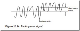
Tracking is ensured by the horizontal actuator of the two-axis device for small adjustments and by the sled motor for larger adjustments. The sled motor keeps the optical head moving along with the spiralling track and if necessary introduces a ‘jump’ when a new sector is selected for reading. The sled error (SE) is calculated inside the servo DSP which monitors the TE signal (Figure 20.24). The low-frequency component of the tracking error (TE) signal is caused by the gradual spiralling of the track towards the out- side circumference. It is used to control the sled motor. The high-frequency
component, on the other hand, represented by spikes, is caused by the jerky track itself. It is used to control the tracking actuator.
Typical servo control chip
Focus and tracking error signals, FE and TE arrive from the RP amplifier/ digital servo at pins 29 and 23, respectively (Figure 20.25). They are processed by the servo DSP to produce a pair of positive and negative con- trol signals at pins 1, 3 and 5, 7. These are then fed to the focus and track coils drivers to position the objective lens for correct focus and track. The system provides for three motor servo control: loading, sled and spindle. The loading motor drive is controlled by a single signal (pin 39) to open and close the tray. The purpose of the sled motor is to keep the optical unit moving along with the spiral track. The low-frequency component of the TE signal is used to calculate a sled error, SE. This error is then used to pro- duce two pulse width modulated (PWM) signals that are fed into the sled motor drive. The drive mute is used to turn the sled motor off during such activities as focus search and pause.
The error signals for the spindle motor are generated by the RF proces- sor. At the RF processor, the data bit rate emanating from the optical head is compared to a master clock. If there is a difference, the RF processor gen- erates two error signals: a phase error and a speed error. These are fed into the servo DSP (pins 18 and 19) which processes them and produces a PWM signal for the spindle motor drive (pin 71) which in turn produces positive and negative signals to control the speed of the motor. These two signals are fed back via a summing amplifier to the servo DSP (pin 17) to complete the servo loop. The servo DSP is set up and controls the system control microprocessor via a 2-bit address bus (pins 80, 81), an 8-bit data bus (pins 82–89), Read, Write, IRQ and chip select (CS). The 27 MHz sys- tem clock is fed at pin 95 and a chip reset is at pin 68.
