Flat panel iDTV
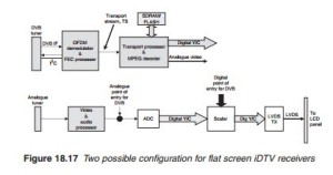
There are two possible circuit configurations for iDTV flat screen displays (Figure 18.17). As was explained in earlier chapters, for flat display panels, LCD or plasma, the incoming video signal must be converted to the native resolution of the panel before it can be displayed. Formatting involves I/P conversion, scan conversion and image conversion and it may be carried out by a number of different chips or more likely by a single chip usually referred to as a scalar chip. Formatting being a processing activity requires the video input to be in a digitised format. Since the video signal extracted from the DTTV decoder is in digital form, it is possible to feed this DVB video directly into the formatting section. However, a second configuration is possible. This configuration involves converting the DVB video signal into an analogue format resulting in two analogue video signals, DVB video and analogue video. An analogue/DVB video switch then selects between two similar signals to feed into the scalar.
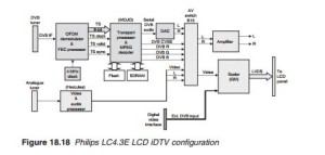
An example of the second configuration employed by a Philips LC4.3E chassis is illustrated in Figure 18.18.
An example of the other configuration employed by a Panasonic LCD television is illustrated in Figure 18.19.
The HD decoder box
The front end of HD satellite decoder (Figure 18.20) is the same as that used for SD broadcasting. The same goes for the transport demultiplexer. The difference arises in the audio and decoding section. With HD reception, a multi-standard decoder chip is used capable of decoding both HD advanced video coding (AVC) and stereo/surround sound advanced audio coding (AAC) as well as MPEG-2 video and audio packets.
A large SDRAM memory store is necessary. The picture is reconstructed into Y, CR and CB, and the sound is reconstructed into a serial PCM (digital) with associated control signals (L/R clock, sampling rate and bit or sys clock). The video and audio signals are fed into a HDMI encoder (or transmitter) which converts them into a serial bitstream suitable for connection to an HD ready television receiver. Also available is SPDIF sound on a coaxial or optical port as well as component video, SCART and so on.


