VIDEO DATA PROCESSING
We saw in Chapter 12 the huge volume and fast rate of data involved in ‘raw’ digitised TV signals, and how the bit-rate can be reduced for transmission. DVC does not compress the data as much as DTV transmission systems for two basic reasons: it is often required, dur- ing replay, to freeze or ‘trick-play’ the picture, or to edit off-tape sequences, and highly compressed datastreams do not lend themselves readily to these; and tape capacity in a DVC cassette is not at so much of a premium as bandwidth in a commercial transmission medium. The bit-rate is reduced by a factor of about five in DVC format – compare with DTV, factor typically 20.
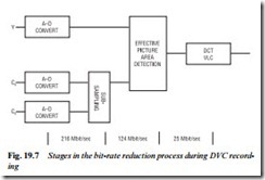
Fig. 19.7 shows how the bit-rate is reduced. For a 625/50 picture the luminance is sampled at 13.5 MHz rate and quantised to 8 bits,
while the Cr and Cb colour-difference components are sampled at 6.75 MHz at 8-bit depth, making a total for the 4:2:2 signal, of 216 Mbit/sec. Subsampling of the chroma components reduces the bit-rate to about 162 Mbit/sec, and subsequent removal of blanking and sync periods gets it down to around 124 Mbit. The DVC protocol now reduces the bit-rate to about 25 Mbit/sec for recording. DVC compression is only applied within individual frames (intra-frame coding) and not between them: temporal redundancy is tolerated for the sake of editing and trick-mode replay.
The special redundancy removal is based, just like the MPEG-2 system described on page 244, on 8×8 pixel macroblocks and discrete cosine transform. As before, the DCT process converts block values to frequency coefficients and then scans them in zig-zag fashion (Figs 12.6 and 12.7) to permit variable-length coding, using a look-up table common to record and playback systems.
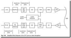
Fig. 19.8 outlines the DVC record and replay processes. After A−D conversion the data is shuffled by taking macroblock samples from widely spaced areas of the picture and assembling them into a seemingly random order for the DCT and variable-length coding processes. Here the bit-rate of five macroblocks is reduced from about 15 kbit to 3 kbit, after which the data is deshuffled once more to restore correct order (left-to-right and top-to-bottom scanning) for recording on tape: the top of the picture is recorded first, and the picture bottom at the run-off (top of tape) of the last of the 12 head scans per frame. Picture LHS data is written to tape at the entry side of head scan, and picture RHS data at the exit side. The reason for the shuffle/deshuffle process (which has to be repeated in playback)
is to avoid statistical distortion due to compression ratio bias, and to give best-possible still-frame and ‘trick’ replay.
Next a form of Reed−Solomon error correction code is applied to armour the data against the relatively vulnerable (primarily to dropout) record/play processes. Now the datastream is modulated and passed via a recording amplifier and rotary transformer to the tape heads, whose gaps are cut at large (±20°) azimuth angles to minimise crosstalk effects.
On replay the off-tape signal is amplified and equalised, the latter to give best possible discrimination between 0 and 1 symbols, then the various components of the TDM datastream are strobed out by the synchronous detector stage. The video sector now undergoes error detection and repair in the ECC section; any data which is missing or corrupt beyond repair is deleted here and replaced by previous (good) data from an adjacent picture area in similar fashion to that of an analogue dropout compensator.
Next the data is shuffled once more, using the same algorithm as on record, and then expanded back to its original form, with variable- length decoding and deshuffling, using the same 5 Mbit SRAM as was used on record – indeed the same ICs, memories etc. are used on record and replay for many such functions, being designed to reverse their role when commanded to do so by the system control section. Now the video signal is ready for D−A conversion into composite video, S-video and (in some cases) RGB streams for output to a TV set or monitor.
Firewire interface
While D−A conversion and PAL encoding gives DVC format compat- ibility with analogue equipment (and at some stage every picture we watch has to be converted to analogue form), for applications where the picture will be further processed or stored in digital form it is best transferred in digital form. Examples are off-line (non-linear) editing, image manipulation and enhancement, printing of still images etc. involving a computer, and ‘lossless’ copying to another digital tape or disc.
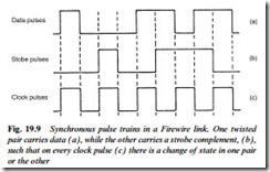
For these purposes a serial data link is available: IEE1394/Firewire. It is a very fast and versatile system with bit-rates to 400 Mb/sec or more, and applications in TV, VCR, PC, printer, scanner, and cable TV delivery systems. The data is carried in a special cable having a power line conductor-pair capable of carrying (maximum) 1.5 A at up to 40 V d.c.; and two individually screened twisted-pair cables which carry the data, see Fig. 19.9. One pair conveys data in NRZ
(non-return to zero) form, while the second pair takes strobe pulses. Exclusive-OR gating of the two pulse trains provide the clock- timing pulses. The pulse amplitude of each train is 220 mV, centred on a bias voltage of 1.86 V with respect to ground.
Firewire datastreams have two components, a slow asynchronous one-way data train for control purposes, and – time-interleaved with it – a very fast isochronous one which carries the ‘real’ data in variable-length packet form, with header, ident, address, data and CRC-check components. Isochronous means that a master clock in the controlling device governs the data-transfer rate, and hence the data-detection system at the receiving end. The Firewire link system is bi-directional and ‘intelligent’, serving a network of up to 63 devices each addressed by a 6-bit ID code; many such networks can be linked to embrace a maximum of 64 500 devices. A negotiation and arbitra- tion process is used for access control in Firewire networks, governed by a ‘bus-management’ system embodied for simple applications in the interface chips, and in more complex ones in a PC or control microprocessor.


