TAPE SCANNING
The DVC tape has a 180° helical wrap around the upper drum, similar to that of analogue formats. The very small (21.7 mm diameter) drum contains two heads with very short gaps: the track pitch is about 10 microns, one-fifth of the width of an analogue VHS video track, and only practical, noise-wise, because the digital system has only to recognise two states, 0 and 1, in the recorded signal.
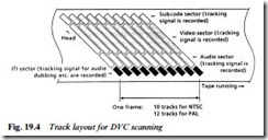
Drum rotational speed is very high, at 9000 r.p.m., to give a writ- ing speed of almost 10 metres/sec on the short scan around the drum half-periphery, and (for 625/50-standard machines) there are twelve head scans/tracks per TV field, as shown in Fig. 19.4. This is made possible by a digital store in the recording circuit which feeds ‘bursts’ of data, corresponding to about 48 TV scanning lines, to the head drum in synchronism with its rotation and with the other signals recorded in sequence along each tape track as shown in the diagram. For 625/50 recordings the effective data area of a complete head scan
is 135 kbit, divided sequentially into the four sectors ITI, audio, video, and subcode, each of which will be examined next.
ITI sector
The first data written to tape in the head scan is ITI, primarily the reference signal for absolute track height and a tracking signal for audio dubbing etc. This data is used by the VCR itself in playback, and no user information goes on here. It does, however, facilitate video insert editing without disturbing existing sound, something not possible with conventional analogue VCR formats. Fig. 19.5 shows a video-only insert.
Audio sector
Audio data occupies the next segment of the head scan, again chopped, stored and ‘strobed’ into the time-division-multiplexed
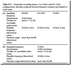
record data fed to the writing head. There are two recording modes, 16-bit for high sound quality in a 2-channel stereo system, as shown in Table 19.2a; and 12-bit, suitable for dubbing, whose details are given in Table 19.2b. Audio AUX data is recorded in the audio sec- tor too.
Video sector
The video data on tape carries information on Y and C signals, time- compressed by DCT variable length coding, and error-protected by a Reed-Solomon code. In addition to the picture data, other information is recorded in the video sector of the magnetic track: date and time of recording; widescreen-mode flag; input source; camera information, such as F-stop setting; and others. These indications can be displayed or not as the viewer chooses, and the widescreen flag can be made to switch a TV set or monitor to the appropriate display mode.
Subcode sector
The last signal in the TDM bouquet recorded by the head as it approaches the end of its slant scan across the tape is the subcode sector – Fig. 19.4 again. The subcode sector is primarily concerned with editing and still-picture record and playback. The time code gives each picture frame its own address in terms of hours, minutes, seconds and frames. These references can be made up into an EDL (Edit Decision List) and used by an auto-editor to compile a master tape.
Other components of the subcode sector are the Index ID, a cue signal for finding the desired scene, shot or programme; and the PP-ID, a mark recorded automatically whenever the camera is set to still frame/photo mode. It identifies each still shot on the tape and can be used, for instance, for automatic frame grabbing and picture printout through a video printer.
Head tracking
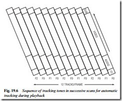
During each recording head scan of the tape a pilot tone is recorded, in similar fashion to that described on page 273 for the Video 8 ATF system. In DVC format three frequencies (F0=0; F1=465 kHz; F2=697 kHz) are recorded on alternate tracks in the sequence F0, F1, F0, F2 and so on – see Fig. 19.6. During playback the tracking
tones are filtered out of the replay signal and used to control the tracking servo such that the crosstalk levels of adjacent tracks become equal, signifying optimum track-centre scanning.
DVC specification
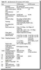
The data given so far, and much more besides, is set out, for the Standard Definition format, in Table 19.3.
