Enhanced-ALiS
Like all interlaced picture re-production, ALiS suffers from intra-frame line flicker. Although flicker with ALiS is far less than that experienced with a CRT, there still remains an element of it which is removed with the enhanced-ALiS (e-ALiS) developed by Fujitsu. Such displays are fre- quently known as A1 panels. The most outstanding characteristic of the new e-ALiS display type is that they once more offer progressive driving.
For ALiS technology to be used with progressive driving, it is necessary to control two pixel lines both simultaneously and independently using one electrode only. This is made possible by the introduction of horizontal barriers to separate the cells into individual units that can be pre-charged independently from each other.
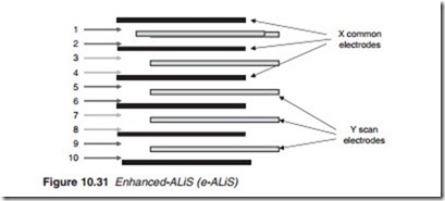
With e-ALiS, the display is broken up into pairs of visible lines allocated to two groups: Group 1 comprising lines 1–2, 5–6, 9–11 and so on and group 2 comprising lines 3–4, 7–8, 11–12 and so on as shown in Figure 10.31. A 4-phase drive cycle is used:
Erase − Pre-condition (or reset) − Address − Discharge
The sequence begins with a simultaneous X–Y erase pulse to all lines and pixels (Figure 10.32). This is followed by the pre-conditioning phase to initialise lines in group 1 to be ready for the addressing phase. Pre- conditioning is achieved by applying a common reset pulse (Reset 1) to the Y electrodes while at the same time applying a pulse to the X elec- trodes involved in group one, line by line. A small discharge takes place which creates a small pre-conditioning wall charge. This is followed by the address phase in which the pre-conditioned pixel cells are addressed line- by-line and primed to be ‘ON’ or ‘OFF’. Next, group 2 (line-pairs 3–4, 7–8, 11–12, etc.) are pre-conditioned and addressed in a similar way. Once both groups of line-pairs are addressed and the cells are selected for discharge, a sustain pulse is applied to discharge all selected cells simultaneously. The process is then repeated for the next SF and so on. Thus, while inter- lacing is used in the address phase, the discharge or light emission is simultaneously eliminating line flicker completely.
Pioneer’s Waffle rib and T-shaped structured panel
A number of developments have taken place and continue to take place in the structure of a plasma panel to improve its brightness and contrast. Box- shaped cells are commonly used to provide a larger effective phosphor sur- face and hence higher brightness. Pioneer developed the Waffle-structured Rib curbing like the surface of a waffle and the T-shaped electrode struc- ture. The deep cells are encapsulated with horizontal ribs so emitted light won’t escape into neighbouring cells. Further improvement was produced with the addition of ‘Crystal Emissive Layer’ to increase luminous effi- ciency. Figure 10.33 shows the basic layers of a modern Pioneer plasma display panel.

