Valve construction
Valve sizes
Valve sizes are normally designated by the size of the port tappings. This gives a match between the pipe size and the valve size, so that a 1/4 in valve would have ports tapped to bore pipe, threaded to take a 1/4inBSPorNTPthread(in the Britishor American former designation).
The ISO standard thread specifies a 1/4 BSP thread as G1/4 for a parallel thread and R1/4 for a taper thread and this has been adopted through Europe. Most suppliers of valves use the G designation throughout the range of sizes, which are the same as the equivalent BSP threads.
Most pneumatic valves are tapped with parallel G thread sizes, because aluminium, zinc alloy and other light weight materials are not strong enough to seal on taper threads, particularly where connections are being constantly made and remade.
Valve configurations
Valves are available in both in-line and sub-base mounted versions. In-line versions have the ports machined into the body of the valve for direct connection of the inlet, outlet, exhaust and pilot lines; sub-base mounted valves are made in block form for mounting on a common baseplate or manifold, and all lines are connected into the base.
With sub-base valves there are normally no tapped connections into the body of the valve itself; all ports are brought to the valve base and connection is completed by mounting on a matching sub-base or manifold carrying the corresponding ports. Joints between the base and the valve are sealed with gaskets or 0-rings. Sub-base mounted valves are designed to accommodate individual valves; manifolds are designed to accommodate a number of valves on a common mount.
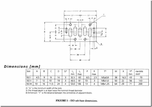
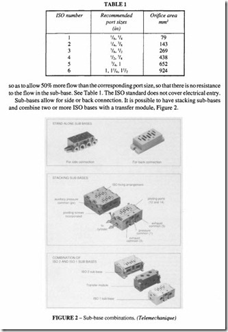
Most bases and port configurations are standardised to ISO specification ISO 5991/1 (BS 7389-1), Figure 1, so that valves of different manufacturers can be interchanged on the same base. Note that this standard applies to 5 port valves, with pilot connections only. It does not necessarily follow that the overall dimensions of the valve will be the same, only that the matching port configurations will be the same, nor does it follow that the flow characteristics will be identical. A feature of the ISO sub-base is that the slots are designed
For miniature valves smaller than ISO 5991 size I,sub-bases are made either to the manufacturer’s own design or to the German standard VDMA 24563. The latter standard, where it overlaps the smallest ISO size (ISO I) has a smaller body. So, for example, ISO I has a body width of 43 mm, the VDMA standard has body widths of 18 and 26 mm.
Other sub-base patterns may be found, for example DIN, CNOMO and ANSI as well as manufacturer’s own designs.
Manifold mounting
In-line valves can be mounted together on a manifold for compact installations. The valve body has to be designed to allow for connection in this form. The inlet and exhaust connections are in the manifold and the cylinder ports are in the valve body. The number of valves that can be connected in this way can be large; depending on the manufacturer there can be 20 or more. One typical type is shown in Figure 3.
Sub-base valves can either have a single sub-base block or more usually be manifolded together on a manifold block with all the connections in the sub-base.
Manifold valves are usually pilot or solenoid operated (or both in the same block). It is not usually possible or practical to manifold together manually or mechanically operated valves.
Valve operation
Movement of a valve element (spool poppet or slide) from one position to another can be accomplished by any of the following methods:
• Manually by a push button, lever or pedal
• Mechanically by spring, plunger or roller
• Electrically by a solenoid or electric motor
• By fluid pressure (air or hydraulic operation)
• By self actuation
Standard methods of designating these in a circuit diagram are shown in Figure 4. See also the chapter on Graphical Symbols.
Manual and mechanical operation are basically similar in that a mechanical force is applied directly to the moving element. With a lever, the mechanical advantage can be adjusted to allow for the available force or displacement. It may be necessary to incorporate a spring detent to hold the moving element in a particular position (either of the selected positions or neutral). It may also be necessary to incorporate a spring return so that the valve is held in the selected position only so long as the actuating force is applied.
Manual and mechanical operation
These valves may have direct or indirect operation of the spool or poppet. In the case of direct operation, the spool is actuated by a mechanism or by human actuation (hand or pedal).
Indirectly operated valves are where the spool is moved by the application or removal of an air supply on the end of a valve spool or on a pilot piston. The thrust exerted by the air pressure acting over the surface area of the pilot piston overcomes the friction of the valve and any return spring that may be fitted and causes the spool to move. Valves can be either dead movement or spring return.
Pedal valves are foot operated, suitable for such purposes as operating machinery or safety guards. They can be operated by a cam mechanism that prevents over-travel of the spool. A compact unit with a small movement gives less operator fatigue during repeated operations.
Two handed control units are intended to operate a pressure operated spring return valve which controls an air cylinder which may be used directly to move a press or other machine. The control unit protects the person operating the buttons. If there is a danger of persons being injured, guards or interlocks are necessary.
Figure 5 shows a two handed control unit which has push buttons built into the end covers; the positioning of the push buttons is arranged so that they cannot be operated by one hand nor readily bridged by a tool. The unit should be positioned so that it cannot be operated by one hand and another part of the body. In addition the push buttons are shrouded to guard against accidental operation, while it is still possible to wear gloves. The control unit will supply pilot pressure only if the two buttons are pressed within one second of each other. No signal will be given if one button is continually depressed or under any circumstances other than the two buttons being pressed together.
Manual- and mechanically-operated valves can be supplied with a variety of operating
mechanisms, examples of which are shown in Figure 6. Mechanical operation includes operation by palm, plunger, roller, trip, foot, push button, switch, key, rotary selector.
Air operation
In the case of air operation, this may be direct, indirect or pilot operated. In a direct air operated valve, signal pressure is applied directly to a piston formed by an end cap or full bore section on the ends of the valve spindle. Air operated movement can be in one direction (with spring return) or in both directions; either method is suitable for two position valves.
For three-position valves, a central position can be given by applying signal pressure to both ends simultaneously, releasing pressure on one side or the other to achieve movement. Alternatively, the spool can be spring biased towards the central position and pressure applied to one side or the other with the opposite side vented.
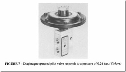
The signal pressure is often substantially less than the line pressure carried by the valve, so that lower signalling pressures can be used. However if the available signal pressure is too low, the valve may be operated indirectly by a low pressure signal through a suitable actuator such as a diaphragm, Figure 7. One-direction or two-direction actuation is possible by feeding an air signal to one or both sides of the diaphragm simultaneously. Pilot-operation provides the main valve with a pneumatic actuator capable of moving the valve when a low pressure signal is applied.
Air-actuated valves can be designed to provide a delay in shifting the valve after admission of pilot air (timed-in) or cessation of the pilot supply (timed-out). For timed in operation, air is admitted slowly so that a few seconds are required for enough air to accumulate in the head to shift the valve. For timed-out operation the process is reversed, causing a delay in the exhausting of the pilot air from the head. The valve therefore remains actuated for a few seconds after the pilot supply air has been turned off. The delay mechanism can be adjusted to provide variable time delays. This kind of valve introduces the possibility of having an automatic sequence of operations without the need for operator
intervention; pilot air can be supplied by some other operation and the subsequent steps can be delayed for a preset time.
Solenoid valves
These valves are becoming increasingly important with the extension of computer control and other electrical control systems for automation and robotics.
When control is to be initiated from an electrical signal, some form of solenoid operation is required in order to generate the force necessary to operate the valve. A simple solenoid valve comprises an integrally mounted solenoid with an armature directly linked to the valve movement. Alternatively (and commonly) in order to minimise the electric power required, the solenoid may only act as a pilot control, the valve itself then being operated by the fluid pressure available.
Solenoid poppet valves
By arranging the solenoid armature to work in a sealed tube with the solenoid coil enveloping it, the sealing glands can be dispensed with, simplifying the construction and eliminating one source of leakage. The principle is illustrated in Figure 8.
The valve is T-shaped with two ports opposite each other, while the third is at right angles to them. The plunger of a corrosion-resistant ferrous material is spring-biased so that when un-energised it closes the lower orifice while leaving the other open.
When energised, the plunger is pulled up so that the lower orifice is opened and the upper closed. The spring can be arranged to bias the plunger in the opposite direction. The plunger is provided with plastic valve discs, nylon or synthetic rubber. Because the plunger is unbalanced, the force due to the pressure must be limited. The size of the orifice and therefore the flow and pressure drop is related to the power. Sealing is normally bubble tight, but this is dependent on the cleanliness of the air.
Glandless valves may be installed in any position and will withstand appreciable shock loads. Response time to energise or de-energise a miniature valve of this kind is of the order of 5 ms on 24 V d.c.
The valve as illustrated is an in-line type but sub-base or manifold versions are also available.
Solenoid pilot valves
An example of this type is shown in Figure 9. The solenoid controls a pilot supply for the indirect operation of the main spool. When the solenoid is de-energised, the pilot air is blocked off and the pilot chamber is vented to exhaust by way of axial slots in the armature of the solenoid. Energising the solenoid applies a pilot air to the pilot piston on the spool. Thus a small pilot solenoid operates a spool that would otherwise require a large solenoid with its armature directly connected to the spool. The single solenoid-operated spool valve is normally supplied with a spring return, although any other mechanism could be fitted to reset. A second solenoid could be used which would give a latching function from two independent pulses. By fitting low power valves to a larger pilot operated valve, low power, high flow valves can be produced.
Single- and double-solenoid valves can be mounted on an ISO 5599 standard sub-base or on a manifold as described above.
The pilot air can come through a separate port which allows extra flexibility of control
in that both pilot air and an electrical signal have to be present before spool movement is possible. Ifthat is not required, the pilot air can come from an internal passage in the valve.
Impulse solenoid valves
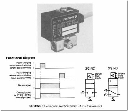
These are a type of solenoid valve which move on the application of an impulse power signal and therefore consume no power in the steady state. The advantages of these zero watt coils are no continuous power consumption, negligible heating effects and safety, which is realised because the valve is bi-stable, remaining in its last position in the event of a power failure. This is of particular value in battery operated equipment.
A typical valve is shown in Figure 10. The actuator consists of an epoxy-encapsulated coil containing windings for pull and throw function. A permanent magnet incorporated is completely separated from the fluid medium.
The impulse coil for plunger-armature systems works in such a way that switching is achieved by means of a short power impulse on the electro-magnet. The permanent magnets enable the valve to retain this position without the need for continuous application of electrical energy. Only when a second impulse is applied does the valve switch back. No power is required to maintain the operated position. Consequently the heating effect of the coil is negligible and the seal materials of the valve are not subjected to any thermal loading. The advantages of this impulse coil can be appreciated in applications involving the control of multi-way pneumatic valves.
Valves of traditional design require an electrical control unit for switching pneumatic cylinders, which have to provide a continuous electrical or pneumatic signal during the entire period of solenoid valve operation. The impulse coil simplifies matters considerably when used in conjunction with position sensors for the control of pneumatic cylinders.


