■ RADIATION HEAT TRANSFER: DIFFUSE, GRAY SURFACES
The analysis of radiation transfer in enclosures consisting of black surfaces is relatively easy, as we have seen, but most enclosures encountered in practice involve nonblack surfaces, which allow multiple reflections to occur. Radiation analysis of such enclosures becomes very complicated unless some simplifying assumptions are made.
To make a simple radiation analysis possible, it is common to assume the surfaces of an enclosure to be opaque, diffuse, and gray. That is, the surfaces are nontransparent, they are diffuse emitters and diffuse reflectors, and their radiation properties are independent of wavelength. Also, each surface of the enclosure is isothermal, and both the incoming and outgoing radiation are uniform over each surface. But first we review the concept of radiosity discussed in Chap. 21.
Radiosity
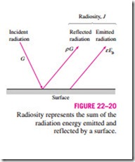
Surfaces emit radiation as well as reflect it, and thus the radiation leaving a surface consists of emitted and reflected parts. The calculation of radiation heat transfer between surfaces involves the total radiation energy streaming away from a surface, with no regard for its origin. The total radiation energy leaving a surface per unit time and per unit area is the radiosity and is denoted by J (Fig. 22–20).
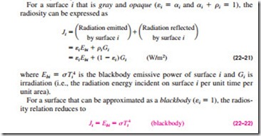
For a surface i that is gray and opaque (ei = ai and ai + ri = 1), the radiosity can be expressed as
That is, the radiosity of a blackbody is equal to its emissive power. This is expected, since a blackbody does not reflect any radiation, and thus radiation coming from a blackbody is due to emission only.
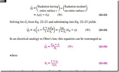
Net Radiation Heat Transfer to or from a Surface During a radiation interaction, a surface loses energy by emitting radiation and gains energy by absorbing radiation emitted by other surfaces. A surface experiences a net gain or a net loss of energy, depending on which quantity is larger. The net ·rate of radiation heat transfer from a surface i of surface area Ai is denoted by Qi and is expressed as
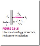
is the surface resistance to radiation. The quantity Ebi – Ji corresponds to a potential difference and the net rate of radiation heat transfer corresponds to current in the electrical analogy, as illustrated in Fig. 22–21.
The direction of the net radiation heat transfer depends on the relative magnitudes of Ji (the radiosity) and Ebi (the emissive power of a blackbody at the temperature of the surface). It will be from· the surface if Ebi > Ji and to the surface if Ji > Ebi. A negative value for Qi indicates that heat transfer is to the surface. All of this radiation energy gained must be removed from the other side of the surface through some mechanism if the surface temperature is to remain constant.
The surface resistance to radiation for a blackbody is zero since ei = 1 and Ji = Ebi. The net rate of radiation heat transfer in this case is determined directly from Eq. 22–23.
Some surfaces encountered in numerous practical heat transfer applications are modeled as being adiabatic since their back sides are well insulated and the net heat transfer through them is zero. When the convection effects on the front (heat transfer) side of such a surface is negligible and steady-state conditions are· reached, the surface must lose as much radiation energy as it gains, and thus Qi = 0. In such cases, the surface is said to reradiate all the radiation energy it receives, and such a surface is called a reradiating surface. Setting Qi = 0 in Eq. 22–25 yields
Therefore, the temperature of a reradiating surface under steady conditions can easily be determined from the equation above once its radiosity is known. Note that the temperature of a reradiating surface is independent of its emissivity. In radiation analysis, the surface resistance of a reradiating surface is disregarded since there is no net heat transfer through it. (This is like the fact that there is no need to consider a resistance in an electrical network if no cur- rent is flowing through it.)
Net Radiation Heat Transfer between Any Two Surfaces
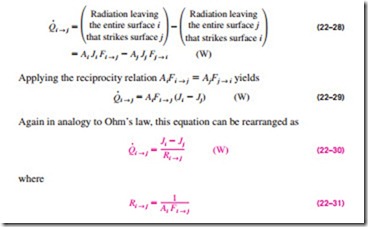
Consider two diffuse, gray, and opaque surfaces of arbitrary shape maintained at uniform temperatures, as shown in Fig. 22–22. Recognizing that the radios- ity J represents the rate of radiation leaving a surface per unit surface area and that the view factor Fi ® j represents the fraction of radiation leaving surface I that strikes surface j, the net rate of radiation heat transfer from surface i to surface j can be expressed as
is the space resistance to radiation. Again the quantity Ji – Jj corresponds to a potential difference, and the net rate of heat transfer between two surfaces corresponds to current in the electrical analogy, as illustrated in Fig. 22–22. The direction of the net radiation heat transfer between two sur·faces depends on the relative magnitudes of Ji and Jj. A positive value for Qi ® j indicates that net heat transfer is from surface i to surface j. A negative value indicates the opposite.
In an N-surface enclosure, the conservation of energy principle requires that the net heat transfer from surface i be equal to the sum of the net heat transfers from surface i to each of the N surfaces of the enclosure. That is,
The network representation of net radiation heat transfer from surface i to the remaining surfaces of an N-surface enclosure is given in Fig. 22–23. Note that (the net rate of heat transfer from a surface to itself) is zero regardless of the shape of the surface. Combining Eqs. 22–25 and 22–32 gives
which has the electrical analogy interpretation that the net radiation flow from a surface through its surface resistance is equal to the sum of the radiation flows from that surface to all other surfaces through the corresponding space resistances.
Methods of Solving Radiation Problems
In the radiation analysis of an enclosure, either the temperature or the net rate of heat transfer must be given for each of the surfaces to obtain a unique solution for the unknown surface temperatures and heat transfer rates. There are two methods commonly used to solve radiation problems. In the first method, Eqs. 22–32 (for surfaces with specified heat transfer rates) and 22–33 (for surfaces with specified temperatures) are simplified and rearranged as
Note that Qi = 0 for insulated (or reradiating) surfaces, and = Ji for black surfaces since ei = 1 in that case. Also, the term corresponding to j = i will drop out from either relation since Ji – Jj = Ji – Ji = 0 in that case.
The equations above give N linear algebraic equations for the determination of the N unknown radiosities for an N-surface enclosure. Once the radiosities J1, J2, . . . , JN are available, the unknown heat transfer rates can be determined from Eq. 22–34 while the unknown surface temperatures can be determined from Eq. 22–35. The temperatures of insulated o·r reradiating surfaces can be determined from sTi4 = Ji. A positive value for Qi indicates net radiation heat transfer from surface i to other surfaces in the enclosure while a negative value indicates net radiation heat transfer to the surface.
The systematic approach described above for solving radiation heat transfer problems is very suitable for use with today’s popular equation solvers such as EES, Mathcad, and Matlab, especially when there are a large number of surfaces, and is known as the direct method (formerly, the matrix method, since it resulted in matrices and the solution required a knowledge of linear algebra). The second method described below, called the network method, is based on the electrical network analogy.
The network method was first introduced by A. K. Oppenheim in the 1950s and found widespread acceptance because of its simplicity and emphasis on the physics of the problem. The application of the method is straightforward: draw a surface resistance associated with each surface of an enclosure and connect them with space resistances. Then solve the radiation problem by treating it as an electrical network problem where the radiation heat transfer replaces the current and radiosity replaces the potential.
The network method is not practical for enclosures with more than three or four surfaces, however, because of the increased complexity of the network. Next we apply the method to solve radiation problems in two- and three- surface enclosures.
Radiation Heat Transfer in Two-Surface Enclosures
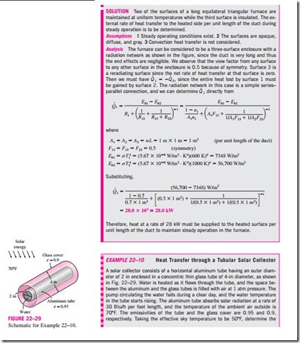
Consider an enclosure consisting of two opaque surfaces at specified temperatures T1 and T2, as shown in Fig. 22–24, and try to determine the net rate of radiation heat transfer between the two surfaces with the network method. Surfaces 1 and 2 have emissivities e1 and e2 and surface areas A1 and A2 and are maintained at uniform temperatures T1 and T2, respectively. There are only two surfaces in the enclosure, and thus we can write
That is, the net rate of radiation heat transfer from surface 1 to surface 2 must equal the net rate of radiation heat transfer from surface 1 and the net rate of radiation heat transfer to surface 2.
The radiation network of this two-surface enclosure consists of two surface resistances and one space resistance, as shown in Fig. 22–24. In an electrical network, the electric current flowing through these resistances connected in series would be determined by dividing the potential difference between points A and B by the total resistance between the same two points. The net rate of radiation transfer is determined in the same manner and is expressed as
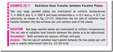
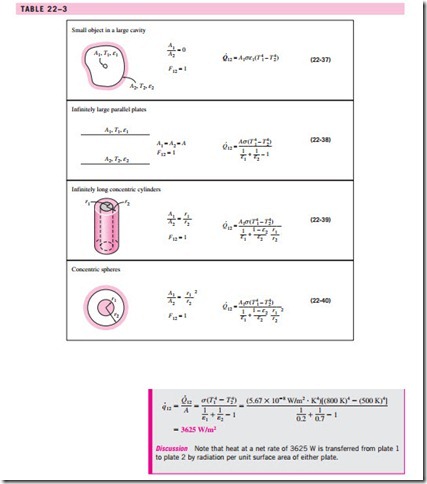
This important result is applicable to any two gray, diffuse, and opaque surfaces that form an enclosure. The view factor F12 depends on the geometry and must be determined first. Simplified forms of Eq. 22–36 for some familiar arrangements that form a two-surface enclosure are given in Table 22–3. Note that F12 = 1 for all of these special cases.
Radiation Heat Transfer in Three-Surface Enclosures
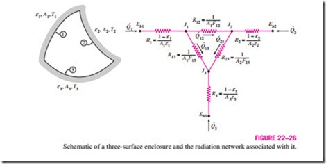
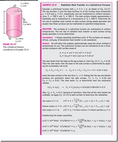
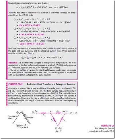
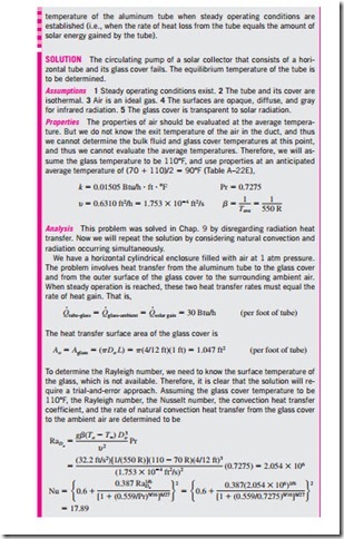
We now consider an enclosure consisting of three opaque, diffuse, and gray surfaces, as shown in Fig. 22–26. Surfaces 1, 2, and 3 have surface areas A1, A2, and A3; emissivities e1, e2, and e3; and uniform temperatures T1, T2, and T3, respectively. The radiation network of this geometry is constructed by fol- lowing the standard procedure: draw a surface resistance associated with each of the three surfaces and connect these surface resistances with space resis- tances, as shown in the figure. Relations for the surface and space resistances are given by Eqs. 22–26 and 22–31. The three endpoint potentials Eb1, Eb2, and Eb3 are considered known, since the surface temperatures are specified. Then all we need to find are the radiosities J1, J2, and J3. The three equations for the determination of these three unknowns are obtained from the require- ment that the algebraic sum of the currents (net radiation heat transfer) at each node must equal zero. That is,
Once the radiosities J1, J2, and J3 are available, the net rate of radiation heat transfers at each surface can be determined from Eq. 22–32.
The set of equations above simplify further if one or more surfaces are “special” in some way. For example, Ji = Ebi = for a black or reradiating surface. Also, Qi = 0 fo·r a reradiating surface. Finally, when the net rate of radiation heat transfer Qi is specified at surface i instead o·f the temperature, the term (Ebi – Ji)/Ri should be replaced by the specified Qi.
