PNEUMATIC SEALS
Seals for valves and cylinders
Seals for cylinders and valves are required to withstand lower pressures than hydraulic seals, normally not more than 10 bar. At the same time operating forces are lower and speeds are higher, which calls for low friction seals. For valves, this implies the use of 0-rings (which may be used in conjunction with harder plastic back-up rings such as PTFE), T-section or similar simple seals. For cylinder pistons and rods, where diameters are larger, pressure energised U-ring seals are preferred.
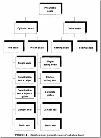
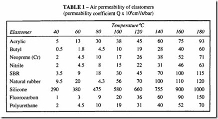
Additionally, in a dirty or abrasive environment, wiper seals can be fitted to piston rods and may be combined with gaiters. See Figure I for the classification of pneumatic seals. High conformity is required from a seal, because air is more difficult to seal than fluids. Pneumatic seals are often used at higher temperatures than seals for liquids, so the permeability of the seal material becomes increasingly important; this may affect the choice of seal material. At normal temperatures, the permeability of most elastomers is low and similar to each other in magnitude, with the exception of silicone rubber. There are however marked differences at elevated temperatures see Table I. All elastomers have operating temperature limits above which they become hard and brittle.
Refer to BS 7714 for general guidance on storage, identification and care when fitting sealing materials.
Seal lubrication
Pneumatic seals are increasingly required to operate in dry (ie with air which is both dry and oil-free) conditions. Such seals are expected to survive on a one-and-only initial lubrication. Most elastomers, with the exception of silicone are appreciably less resistant to ‘dry’ heat than ‘wet’ heat. Unless circumstances preclude the use of lubricated air, it is preferable to install a lubricator in the system, filled with a lubricant chosen to be compatible with the seal materials. The higher the temperature and the faster the speeds, the more important it is to lubricate the air. The absence of oil-mist lubrication can make it difficult to keep a dynamic seal sufficiently well lubricated. There is also the deteriorat ing effect of the oxygen in the air. Manufacturers recommend that once equipment has been used with extra lubrication, this has to be continued.
In the case of a seal operating dry, the apparent permanent set of an elastomer may appear much higher (typically twice as high) than the same seal used on oil. This may call for a greater initial interference when assembling the seal and subsequently higher friction
during the running-in period when the permanent set is taken up. Selection of a suitable interference is more difficult and errors may either cause the seal to continue to bind and develop high friction and wear, or to run-in to a loose fit with consequent leakage.
A permanently binding seal is more likely than a loose seal, particularly if the seal is dimensioned as a dry type and subsequently lubricated by oil-mist. Some oil will be absorbed by the seal and cause it to swell. Consequently a common fault with seals which operate under oil mist lubrication is a failure to provide for the amount of swell the seal is likely to undergo during its conditioning period, which may be of several weeks duration.
Not all seals can be used in the absence of lubrication, so care must be taken when replacing a seal with another of a different specification that the new seal can be used in the prevailing conditions.
Seal materials
The most common materials for pneumatic sealing purposes are artificial rubbers (predominantly nitrile) in a variety of formulations, which may be used with PTFE or other hard plastics. There are also composite seals using more than one material, such as fabric reinforcement, PTFE/rubber combinations and seals with metal inserts. Natural rubber is rarely used because of its temperature limitation (a maximum ofabout80°C). Leather was formerly much used but, despite a variety of tanning processes available, is obsolescent for pneumatic applications. It does however have good wear and extrusion resistance and is self-lubricating, so for special applications may still be found.
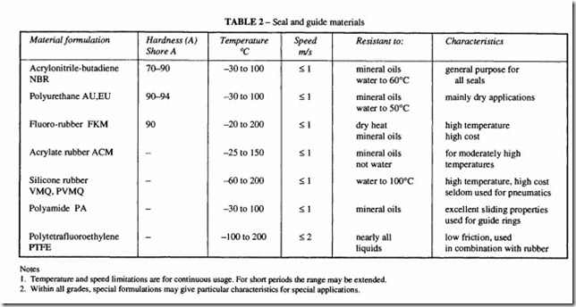
In choosing which of the seal materials are suitable for a particular application, consideration must be given to the temperature regime and the rubbing velocity, see Table 2.
General principles in design of seals
The modern trend in design of sealing systems is to use simple designs and assemblies. U-rings are favoured for larger diameter dynamic applications; and 0-rings and their derivatives are used for static and small diameter dynamic applications; the commonest composite seal is rubber with PTFE. For the large majority of pneumatic sealing duties in cylinders and valves one of these types will be satisfactory, and should be the first choice before trying some other type of seal.
These are ring-shaped seals of circular cross-section, primarily used for static sealing but also for dynamic seals, both axial and rotating. For low pressure (<100 bar) pneumatic seals, the hardness should be about 70 Shore A. For higher pressures, about 90 Shore A hardness should be chosen. If the gap to be sealed is greater than about 0.3 mm, consideration should be given to the use of a backup ring made of PTFE, see Figure 2. The back-up ring acts solely as an anti-extrusion device and is usually split at an angle. BS 5106 gives the sizes of spiral rings and their housings.
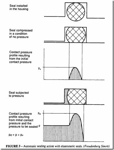
The sealing action of an 0-ring under static pressure is illustrated in Figure 3. The initial pressure on the ring caused by compression of the rubber is increased by the pressure in the fluid; as the fluid pressure increases, the effectiveness of the seal increases so that very high pressures can be sealed. It will be seen from Figure 3 that the locating groove must be large enough both to allow for pressure to act over a large portion of the ring surface and to cater for any volume increase as the seal absorbs water or oil; at least 25% extra volume should be allowed. British Standard BS 4518 (BS 1806 for Imperial sizes) gives
the recommended groove sizes for both hydraulic and pneumatic installations. These or data supplied by the ring manufacturers should be followed as for example in Table 3. The radial compression in this table varies from 10% in the larger sections to 25% in the smaller.
BS 4518 also contains recommendations for the choice of 0-ring size according to the diameter to be sealed.
1- ring seals are typically used for sealing spool valves and for pistons in pneumatic cylinders and similar reciprocating applications. Two regimes are possible:
• With radial compression of the 0-ring. The ring is compressed radially in its groove, with a compression of the cross-section of from 2% to 6%, according to thickness. This ensures good sealing with comparatively long life even with inadequate lubrication. See Table 4 for dimensions.
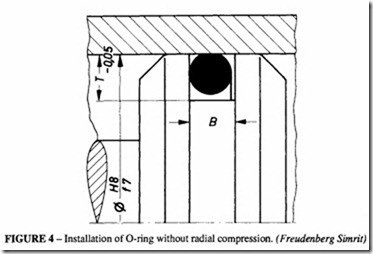
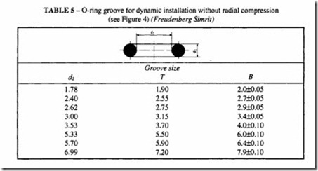
• Without radial compression of the 0-ring, Figure 4. It has a floating fit in the groove and no contact with the base of the groove. There may be some leakage at low
pressure, but the friction and wear are low. The external diameter of the ring should be 2% to 5% greater than that of the cylinder bore. See Table 5.
Ifthe 0-ringis properly assembled and adequately lubricated, and if the groove is correctly dimensioned, it should not twist under reciprocating motion, because the contact area in the groove is far greater than that with the sliding surface. Also, the friction in the groove is static friction which is lower than rubbing friction. However, it has to be admitted that ideal conditions are often not met. If there is any circumferential variation in the friction, some parts of the ring surface may slide while other parts roll, with the result that the ring may eventually suffer a characteristic spiral failure. This is the most common type of ring
failure and is easily recognised. It may also show as a variation in shape and size of the section.
One difficulty that sometimes occurs with poor quality rings is inadequate removal of the flash produced during the moulding process. Even with high grade rings, the flash removal disturbs the surface on which sealing depends.
The advantages of dynamic 0-rings are
• simplicity of housing design
• availability in small sizes, which makes it a first choice for small bores
• bi-directional sealing (in contrast to lip seals which have to be used in pairs)
• lower friction than U-rings.
Non-toroidal 0-rings
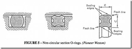
In order to overcomesomeofthedrawbacks in the use of circular section rings for dynamic sealing whilst retaining the simplicity of the groove design, non-circular-section rings
have been developed. They are intended to be direct replacements for standard 0-rings and are designed to be fitted into the same size grooves.
Square section rings are not subject to spiral twist, but they tend to have a high friction caused by the large surface area in contact with the moving component.
This has led to a special form ofO-ring which is of a basic square section with relief on the faces, see Figure 5. This design ensures that the contact area is small, reducing the friction whilst ensuring that spiral twist is impossible. Although the rings can be fitted into standard 0-ring grooves, it is preferable to make the groove widths rather narrower. This is possible because radial compression is accommodated by distortion of the cross-section rather than lateral displacement. When designing from scratch, the groove dimensions recommended by the manufacturer should always be followed.
Although these rings can be used as static seals, there is no real advantage in fitting them.
They can be used forrotary applications where space limitations rule out a rotary shaft seal.
0-ring combinations
A further variation on the basic 0-ring is its use with PTFE slip rings; here the sealing pressure comes from the ring and the PTFE provides a low friction rubbing surface. These seals can be of an external or internal type as in Figure 6. Depending on the manufacturer, they can be used as direct 0-ring replacements fitting into the same standard groove. When comparing a simple 0-ring with aPTFE combination, the frictional force when lubricated is very similar, but when run dry the PTFE is much superior.
U-rings
The U-ring suitably proportioned and in a relatively soft rubber, is capable of providing good sealing in with low friction at low pressures.lt is mainly used in dynamic applications for piston seals. Desirable features are thin lips for response to pressure energisation, generous length for good flexibility, with the lips designed to have low lip loads for low friction and at the same time enough contact area and pre-load for good sealing at low pressure. A square heel section is preferable to minimise heel wear.
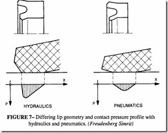
There is a difference in design philosophy between U-rings intended for hydraulic and pneumatic installations. The friction and wear between two bodies sliding over one another is reduced if the surfaces are separated by a layer of I ubrican t. the formation of this film depends on the relative velocity, the viscosity of the lubricant and the pressure profile between the surfaces. The velocity and viscosity are predetermined so the formation of the film is influenced only by the pressure profile. A comparison between the two regimes is shown in Figure 7. Most pneumatic seals get a one and only lubrication during fitting, so it is important that the lubricating film should be retained during the lifetime of the seal. This is in contrast to hydraulic seals which are being constantly lubricated and the seal is required to wipe off the lubricant during each stroke. It can be seen from Figure 7 that the geometry of the two kinds of seal is different; when the pneumatic seal is assembled into its groove, the angle between the seal and surface is symmetrical, ensuring that the lubricant film is maintained.
U-rings are designed to seal from one side only so in double-acting cylinders, two
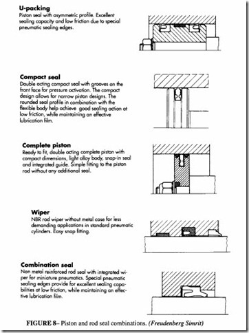
U-rings have to be fitted into the piston. The seals are often separated by a bearing ring which has little sealing function in itself but helps to take side loads. A piston containing these elements can be long, which is undesirable in compact designs, so there has been developed a variety of different piston seals combining several elements in one. Very compact designs consist of an integrated piston and seal, with the seal material bonded to the piston and replaceable as a unit.
Wiper seals
For sealing on the piston rod, a single acting U-packing can be used, similar to a piston seal. An additional feature is required on rods: in dirty and dusty environments, protection has to be given to the rod to ensure that no contamination is drawn into the system. Special wiper seals are used for this purpose; they do not require pressure behind them (indeed if they did, it would indicate that the rod seal was not functioning properly) and rely solely on rubber flexibility to maintain contact with the rod.
Combined piston and wiper seals are also available See Figure 8 for a variety of pneumatic seal combinations.
Housing design
Care should be taken to design the seal housing in accordance with the instructions of the seal supplier. For 0-rings it may be an advantage to make the sides of the groove slightly angled (about 5°) for ease of manufacture. The surface finish of the dynamic sealing surfaces should be 0.4 )lm Ra and on static sealing surfaces 0.8 )lm R., surface texture in accordance with BS 1134. A lower quality of finish is acceptable in the housings,
Considemtion should be given at the design stage to how the seal is to be assembled into its housing. Entry tapers should be provided on the cyIinder bores and piston rods. Special mandrels which cover any threads or sharp edges may be of assistance. During manufac ture, all sharp edges on housings adjacent to the seals must be removed.
