Pascal’s law
Pressure in an enclosed fluid can be considered uniform throughout a practical system. There may be small differences arising from head pressures at different heights, but these will generally be negligible compared with the system operating pressure. This equality of pressure is known as Pascal’s law, and is illustrated in Figure 1.9 where a force of 5 kgf is applied to a piston of area 2 cm2. This produces a pressure of 2.5 kgf cm-2 at every point within the fluid, which acts with equal force per unit area on the walls of the system.
Suppose the base of the left hand tank is 0.1 x 0.1 m to give a total area of 100cm2 . The total force acting on the base will be 250 kgf. If the top of the right hand tank is 1 m x 1.5 m, a surprisingly large upwards force of 37,500 kgf is developed. Note, the size of the connecting pipe has no effect. This principle explains why it is possible to shear the bottom off a bottle by applying a small force to the cork, as illustrated in Figure 1.9b.
The applied force develops a pressure, given by the expression:
Expression 1.10 shows an enclosed fluid may be used to magnify a force. In Figure 1.10 a load of 2000 kg is sitting on a piston of area 500 cm2 (about 12 em radius). The smaller piston has an area of 2 cm2 . An applied force f given by:
will cause the 2000 kg load to rise. There is said to be a mechani cal advantage of 250.
Energy must, however, be conserved. To illustrate this, suppose the left hand piston moves down by 100 em (one metre). Because
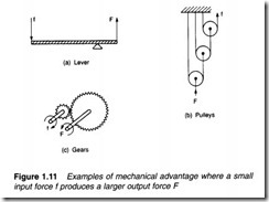
we have assumed the fluid is incompressible, a volume of liquid 200 cm2 is transferred from the left hand cylinder to the right hand cylinder, causing the load to rise by just 0.4 em. So, although we have a force magnification of 250, we have a movement reduction of the same factor. Because work is given by the product of force and the distance moved, the force is magnified and the distance moved reduced by the same factor, giving conservation of energy. The action of Figure 1.10 is thus similar to the mechanical systems of Figure 1.11 which also exhibit mechanical advantage.
The principle of Figure 1.10 is widely used where a large force is required with small movement. Typical examples are clamps, presses, hydraulic jacks and motor car brake and clutch operating mechanisms.
It should be noted that pressure in, say, a cylinder is determined solely by load and piston area in the steady state, and is not dependent on velocity of the piston once a constant speed has been achieved. Relationships between force, pressure, flow and speed are illustrated in Figure 1.12.
In Figure 1.12a, fluid is delivered to a cylinder at a rate of Q cm3 s-1. When the inlet valve is first opened, a pressure spike is observed as the load accelerates, but the pressure then settles back


