Discharge period and pulsations
It should be borne in mind that for an eight-bladed rotor, such as that shown in Figure 3.4, rotating at a typical speed of 20 revolutions per minute (rev/min), a time span of only 0.375 s is available for the material to be discharged from each pocket. The time available for discharge, therefore, is very short, and although this is generally satisfactory for free flowing materials it is generally not for cohesive materials and hence the need for the alternative blow-through valve.
The reciprocal of this time period provides another important operating parameter. The importance of feeding material into a pipeline as smoothly as possible was mentioned above, and it was stated that in a dilute phase conveying system the air would tra- verse a 100 m long pipeline in about 5 s. For the rotary valve being considered above, about 13 pockets of material would be deposited into the pipeline in this period. Such a frequency of pulsations is generally acceptable for most conveying applications and the resulting fluctuation in the air supply pressure is usually acceptable also. Consideration of such pulsations in combustions systems, however, would be recommended.
Air leakage
It is an unavoidable physical characteristic of the rotary valve that, in a positive pressure pneumatic conveying system, there will be a leakage of air across the valve. This occurs in three areas:
• via the returning empty pockets;
• through the various rotor blade clearances between the blade tips and the rotor housing;
• through the gaps between the sides of the blades and the rotor housing.
Positive pressure systems
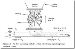
Typical air flows and leakage paths for a rotary valve operating in a positive pressure conveying system are shown in Figure 3.6. Appropriate pressures are also super- imposed to help reinforce the various directions of flow that are also indicated.
The air leaking across the rotary valve by-passes the conveying pipeline and so is not used for conveying, as can be seen from Figure 3.6. This problem is well recognized and most manufacturers of rotary valves supply information on the air leakage rate across their valves so that it can be taken into account. In specifying the air requirements for the blower or compressor, therefore, this leakage air must be taken into account as indicated on Figure 3.6.
Negative pressure systems
Although there will be no air leakage across a rotary valve that is feeding material into a negative pressure conveying system, the total conveying system must be taken into account in this case. With the system operating under vacuum there is plenty of scope for air to leak into the system from other sources. A typical system is shown in Figure 3.7.
With a rotary valve used to continuously off-load material from the discharge hop- per there will be a leakage of air into the system. This has exactly the same influence on the correct specification of the air flow rate required from the exhauster as it does for the blower in a positive pressure system. With vacuum systems care must be taken with air leakage from any source into the system. The problem here is that it will not be seen, and against a background level of noise it may not be heard either.
If such air leakage occurs in a positive pressure system it is unlikely to present any problem at all to the operation of the system. This is because a loss of air along the length of the pipeline will compensate for the expansion of the conveying air, which could actu- ally result in an improvement in performance, provided that the conveying air velocity did not fall below the minimum value for the material. In positive pressure systems,
however, a loss of air from eroded bends and insecure couplings and flanges will be readily observed by everyone in the vicinity because of the dust cloud generated.
Influence of conveyed material
For a 100 mm bore pipeline the air leakage could be as much as 15% of the air supplied. For a material such as plastic pellets it will be even higher, and in smaller diameter pipelines the percentage will be proportionally greater. For a valve operating across a small pressure difference with a very fine material, however, air leakage will be significantly reduced. The magnitude of the loss will depend upon the pressure difference across the valve, the valve size and the rotor tip clearance, the nature of the material being handled, and the resistance to air flow by the head of material over the valve.
The potential influence of the material being conveyed on the leakage of air across a rotary valve is presented in Figure 3.8. This data is obtained from a nominal 200 mm
diameter eight-bladed rotary valve [1]. Tests were carried out with four very different materials and with pressure drop values across the rotary valve of up to about 0.7 bar. In each case the blade tip clearances were set at 0.25 mm. It will be seen from this that fine materials such as polypropylene powder can have a significant sealing effect on the rate of leakage. Polyethylene pellets, being so very permeable, probably offer no resistance at all.
If air leakage across the valve is not taken into account, or if the anticipated leak- age is incorrect for some reason, it can have a marked effect on the performance of the conveying line. If insufficient air is available for conveying the material in the pipeline, as a result of losses across a rotary valve, it is possible that the pipeline will block, for a loss of 10–20 per cent of the total air supply will significantly affect the velocity of the air in the conveying system. Also, if two or more rotary valves feed into a common line, and there is no additional valve over each rotary valve to minimize air losses from those not in use, the air, and hence energy loss, could be very considerable.
Rotor tip clearance is an important variable here. The gradual wear of a valve in use, such that the rotor clearances increase slightly over a period of time, will affect the balance of the air flows shown in Figure 3.8, and consequently affect the conveying line performance. This is one of the reasons why rotary valves are not generally recom- mended for the handling of abrasive materials. It is important, therefore, that rotary valves should be well maintained. The potential influence of blade tip clearance on the leakage of air across a rotary valve is shown in Figure 3.9.
This data was obtained with the same valve reported above with Figure 3.8 [1] and shows a significant effect of blade tip clearance. It is not only with gradual wear of a valve through handling abrasive materials that problems can arise. Consideration must also be given to expansion problems if the air from the blower is not cooled, or the material being conveyed is hot. In these cases particular attention should be given to start up and shut down transient influences on blade tip clearance, because this could become sub-zero and result in valve seizure under certain circumstances.


