Hydraulic coolers and Heat exchangers
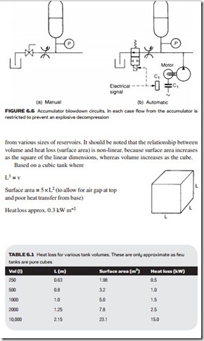
Despite the occasional use of heaters mentioned earlier, the problem with oil temperature is usually keeping it down to the required 50 °C. In small systems, the heat lost through reservoir walls is sufficient to keep the oil cool, but in larger systems additional cooling is needed. Table 6.1 shows typical heat losses
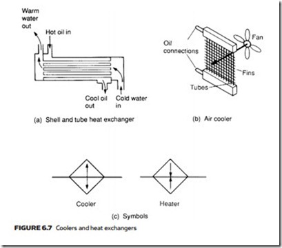
Figure 6.7 shows two types of cooler and their symbols. Water cooling is most common and Figure 6.7a shows the usual form of a shell and tube heat ex- changer which is fitted in the return line to the tank. Note that the cooling water flows in the opposite direction to the oil (giving rise to the term: counter-flow cooler). If the system is open to atmosphere and liable to stand unused in cold weather, protection must be included to prevent frost damage which can result in water-contaminated oil.
Air cooling is also common, shown in Figure 6.7b, with fans blowing air through a radiator matrix similar to those in motor cars (but, obviously, with a far higher pressure rating). Air cooling is noisy and occupies more space than a water cooler, but does not have the danger of contamination from leaks inside a water cooler.

