Beta ratio
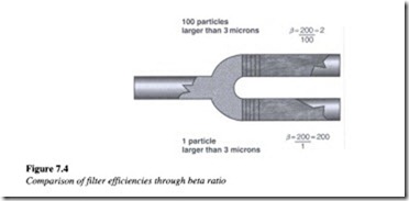
It is a measure of a filter’s efficiency. It is defined as the number of particles upstream from the filter that are larger than the micron rating of the filter, divided by the number of particles downstream from the filter larger than the micron rating of the filter. The example illustrated below demonstrates the concept of beta ratio quite clearly.
From Figure 7.4, it is seen that there are 200 particles upstream from the filter which are larger than 3 !Jm in size. A filter having a lower beta ratio is less efficient because it allows more particles through it. Again referring the example above, it is seen that while the filter at the top allows 100 particles through, only 1 particle is allowed to pass through the filter at the bottom.
The beta ratio for the filter at the top is given by f3 = 200/100 = 2 which is a less efficient value, whereas the beta ratio for the filter at the bottom is given by f3 = 200/ 1 = 200 which is a more efficient value. The following equation is used to determine the efficiency value of a filter, known as beta efficiency.
For example a filter with a beta ratio of 40 would have an efficiency of 1/40 = 97.5%. The higher the beta ratio, higher is the beta efficiency.
Fluid cleanliness level
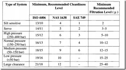
Fluid cleanliness can be defined according to ISO, NAS and SAE standards. ISO 4406 defines contamination levels using a dual scale numbering system. The first number refers to the quantity of particles over 5 IJ per 100 rnl of fluid and the second number refers to the number of particle over 15 IJ per 100 ml of oil.
For example, a cleanliness level of 15/12 indicates that there are between 2’4 and 215 particles over 5 IJ and 2 11 and 212 particles over 15 !J, per 100 ml of fluid.
Let us consider another example based on a I ml fluid sample. A particle count analysis is done for this sample using specific particle sizes of 4Jlm, 6 11m and l4Jlm. By selecting these three sizes, an accurate assessment of the amount of silt from 4Jlm and 6J1m particles can be obtained, while the number of particles above 14Jlm is an indication of the amount of wear type particles in the fluid.
From the ISO 4406 table shown, let us consider a rating of 22/18/13. This indicates the following:
1. 22 indicates that the number of particles greater than or equal to 4 11m in size is more than 20 000 and less than or equal to 40 000, per ml.
2. 18 indicates that the number of particles greater than or equal to 6 11m in size is more than 1300 and less than or equal to 2500, per ml.
3. 13 indicates that the number of particles greater than or equal to 14Jlm in size is more than 40 and less than or equal to 80, per ml.
The ISO contamination code is applicable to all fluid types and provides a universal expression of relative cleanliness, between the suppliers and the users of hydraulic fluid. This code is meaningful, only if it is related to the required cleanliness level of the hydraulic system under consideration. It is usually based on the manufacturer’s requirements for the cleanliness levels in which a component may operate. For example, most gear pumps may sufficiently operate in fluids having a rating of 18116115 ISO, while servo valves require an ISO code 15113/12 or better.
Filter location
Filter location in a hydraulic system is critical to ensuring acceptable levels of fluid cleanliness and adequate component protection. Figure 7.5 shows the location of the various filters in a hydraulic system.
The function of breathers in a hydraulic system is to prevent entry of airborne particles which are drawn into the system due to changes in the fluid level of the reservoir. They are usually mounted on the reservoir. Components such as servo valves which are located immediately downstream of the filter are protected from wear and silting-related problems by pressure filters. These pressure filters are designed to withstand high pump pulsations and the system pressure. Return line filters provide protection against entry of particulate matter when the fluid is returned to the tank. An off-line filter also known as kidney loop is often provided in a hydraulic system especially when fluid circulation through the return-line filter is minimal. Off-line filters operate on a continuous basis. The chief advantage associated with these filters is the flexibility they offer with regard to their placement. Since these filters are independent of the main system, their location in a hydraulic circuit can be chosen in such a way that easy serviceability is ensured.
Filtration methods
There are three basic types of filtering methods used in hydraulic systems.
Mechanical
This type normally contains a metal, a cloth screen, or a series of metal disks separated by thin spacers. Mechanical type filters are capable of removing only relatively coarse particles from the fluid.
Absorbent type
These filters are porous and contain permeable materials such as paper, wood pulp, diatomaceous earth, cloth, cellulose and asbestos. Paper filters are normally impregnated with a resin, to provide added strength. In this type of filter, the particles are actually absorbed as the fluid permeates the material. As a result this method is used for extremely small particle filtration.
Adsorbent type
Adsorption is a surface phenomenon and refers to the tendency of the particles to cling to the surface of the filter. Thus the capacity of such a filter depends on the amount of surface area available. Adsorbent materials used, include activated clay and chemically treated paper.


