Determination of Reynolds number
The friction factor fis primarily dependent on the value of Reynold’s number R,. This is a non-dimensional quantity which governs the flow regime in pipes and heat exchangers as well as in aerodynamic theory.lt is defined as
for any consistent set of units. In particular in SI units, v the local velocity of the flow is in m/s, D the inside diameter of the pipe is in metres, u the kinematic viscosity of the gas is in m2 /s, Jl the dynamic viscosity is in Pas and p the density is in kg/m 3 Note that the value of Jl for air is 17 x 1o-6 Pas at O”C. It varies with absolute temperature in such a way that at 200°C it has a value of 26 x IQ-6 Pas. Linear interpolation between the two values is adequate for most purposes; for more accurate values and for other gases, refer to a standard textbook of physical constants such as Kaye and Laby “Tables of Physical and Chemical Constants” (published by Longman).
The first important result that comes from the determination of Reynold’s number is whether the flow is laminar or turbulent; indeed Osborne Reynold’s (after whom the number is named) is noted for his experiments on finding the transition point between the two kinds of flow. If the number is less than 2000, the flow is laminar; if more than 4000 the flow is turbulent. Between the two is a critical region where it may be one or the other, depending on the roughness of the pipe, changes in section and other destabilising factors. The uncertainty in this statement rarely leads to practical difficulties in the field of pneumatics, except when studying the flow in low pressure fluid logic elements. The flow in pipes is usually well into the turbulent regime.
Determination of the friction factor
For laminar flow the friction factor f is given by
This is known as Poiseuille’s law (or Hagen-Poiseuille’s law) for laminar flow.
For turbulent flow. the position is more complex. Different formulae are used for different industries, particularly for the analysis of pressure drop in long natural gas pipelines; two frequently quoted ones are the Weymouth formula and the Panhandle formula. The flow of liquids through pipes is considered in detail in Valves, Piping and Pipeline Handbook (published by Elsevier) which also contains a discussion of various other standard formulae.
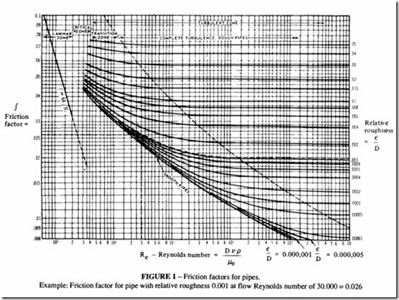
For consistency when studying the flow of air and other gases in the short runs typical of compressed air mains, it is recommended that the values of the friction factor calculated by Moody are used (“Friction Factors for Pipe Flow”, Trans. Amer. Soc. Mech. Engrs., Vol66, Nov. 1944). Figure 1 reproduces the Moody results. The friction factor f can be obtained when both Reynold’s number and the pipe roughness are known. The absolute roughness is the height of an average surface defect on the inside of the pipe, but the significant parameter is the relative roughness, ie the ratio of absolute roughness to pipe diameter.
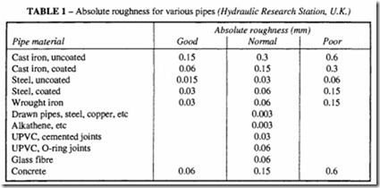
Moody obtained results for a variety of pipes, some of which are rarely found now, such as wood and rivetted steel, and for others such as concrete which are oflittle interest to the
pneumatic designer. The only pipes that the designer is likely to use today are commercial steel, drawn tubing and rubber and plastic hose. Typical values of the absolute roughness are given in Table Lit is important to emphasise that the values presented in that table are for clean, new pipes. Rust and other deposits will form over a period of time; these cause an increase in the absolute roughness and in the worst cases will narrow the inside diameter. Due allowance should be made for these factors at the design stage. About 25% to 50% should be added to the theoretical friction factor to allow for deterioration.
At very large Reynolds numbers, the friction factor is primarily dependent on the value of the relative roughness, as can be seen from Figure I. A condition of complete turbulence is reached when the friction factor is dependent solely on the roughness and no longer on the Reynolds number.


