Shock absorbers
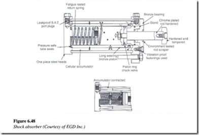
A shock absorber is a device, which brings a moving load to a gentle rest through the use of metered hydraulic fluid. Figure 6.48 shows the cut away section of a common type of shock absorber.
Fat1gue These shock absorbers are mounted, complete with oil. Therefore, they may be mounted in any position or angle. The spring return units are entirely self-contained units and extremely compact. A built-in cellular accumulator accommodates the oil displaced by the piston rod as the rod moves inwards. Since it is always filled with oil, there are no air pockets to cause spongy and erratic action.
Shock absorbers are multiple orifice hydraulic devices. When a moving load strikes the bumper of the shock absorber, it sets the rod and piston in motion. The moving piston pushes oil through a series of holes from an inner high-pressure chamber to an outer low pressure chamber.
The resistance to the oil flow caused by the restrictions, creates a pressure, that acts against the piston to oppose the moving load. Holes are spaced geometrically according to a proven formula which in tum produces a constant pressure on the side of the piston opposite the load. The piston progressively shuts off these orifices as the piston and rod move inward. Therefore, the total area decreases continually while the load decelerates uniformly. At the end of the stroke, the load comes to a rest and the pressure drops to zero. This results in a uniform deceleration and gentle stopping with no bounce back. In bringing a moving load to a stop, the shock absorber converts work and kinetic energy into heat, which is dissipated to the surroundings.
One application of shock absorbers is in the energy dissipation of moving cranes. Here shock absorbers prevent bounce back of the bridge or trolley. The most common applications of shock absorbers are the suspension systems of automobiles.
