A hydraulic or pneumatic system is generally concerned with moving, gripping or applying force to an object. Devices which actually achieve this objective are called actuators, and can be split into three basic types.
Linear actuators, as the name implies, are used to move an object or apply a force in a straight line. Rotary actuators are the hydraulic and pneumatic equivalent of an electric motor. This chapter discusses linear and rotary actuators.
The third type of actuator is used to operate flow control valves for process control of gases, liquids or steam. These actuators are generally pneumatically operated and are discussed with process control pneumatics in Chapter 7.
linear actuators
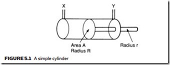
The basic linear actuator is the cylinder, or ram, shown in schematic form in Figure 5.1. Practical constructional details are discussed later. The cylinder in Figure 5.1 consists of a piston, radius R, moving in a bore. The piston is connected to a rod of radius r which drives the load. Obviously if pressure is applied to port X (with port Y venting) the piston extends. Similarly, if pressure is applied to port Y (with port X venting), the piston retracts.
The force applied by a piston depends on both the area and the applied pressure. For the extend stroke, area A is given by πR2. For a pressure P applied to port X, the extend force available is:
The units of expression 5.1 depend on the system being used. If SI units are used, the force is in newtons.
Expression 5.1 gives the maximum achievable force obtained with the cylinder in a stalled condition. One example of this occurs where an object is to be gripped or shaped.
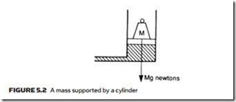
In Figure 5.2 an object of mass M is lifted at constant speed. Because the object is not accelerating, the upward force is equal to Mg newtons (in SI units), which from expression 5.1 gives the pressure in the cylinder. This is lower than the maximum system pressure, the pressure drop occurring across flow control valves and system piping. Dynamics of systems similar to this are discussed later.
When pressure is applied to port Y, the piston retracts. Total piston area here is reduced because of the rod, giving an annulus of area Aa where:
This is lower than the maximum extend force. In Figure 5.3 identical pressure is applied to both sides of a piston. This produces an extend force Fc given by expression 5.1, and a retract force Fr given by expression 5.2. Because Fc is greater than Fr, the cylinder extends.
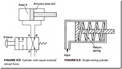
Normally the ratio A/Aa is about 6:5. In the cylinder shown in Figure 5.4, the ratio A/Aa of 2:1 is given by a large-diameter rod. This can be used to give an equal extend and retract force when connected as shown. (The servo valve of Figure 4.40 also uses this principle.)
Cylinders shown so far are known as double-acting, because fluid pressure is used to extend and retract the piston. In some applications a high extend force is required (to clamp or form an object) but the retract force is minimal. In these cases a single-acting cylinder (Figure 5.5) can be used, which is extended by fluid but retracted by a spring. If a cylinder is used to lift a load, the load itself can retract the piston.
Single-acting cylinders are simple to drive (particularly for pneumatic cylinders with quick exhaust valves (see Chapter 4)) but the extend force is reduced and, for spring-return cylinders, the length of the cylinder is increased for a given stroke to accommodate the spring.
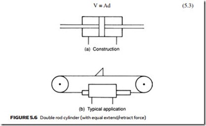
A double rod cylinder is shown in Figure 5.6a. This has equal fluid areas on both sides of the piston, and hence can give equal forces in both directions. If connected as shown in Figure 5.3 the piston does not move (but it can be shifted by an outside force). Double rod cylinders are commonly used in applications similar to Figure 5.6b where a dog is moved by a double rod cylinder acting via a chain.
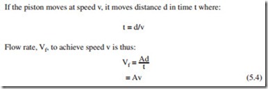
The speed of a cylinder is determined by volume of fluid delivered to it. Sup- pose a cylinder of area A has moved a distance d. This has required a volume V of fluid where:
The flow rate units of expression 5.4 depend on the units being used. If d is in meters, v in meters min−1 and A in meters2, flow rate is in meters3 min−1.
In pneumatic systems, it should be remembered, it is normal to express flow rates in STP (see Chapter 3). Expression 5.4 gives the fluid volumetric flow rate to achieve a required speed at working pressure. This must be normalized to atmospheric pressure by using Boyle’s law (given in expression 1.17).
The air consumption for a pneumatic cylinder must also be normalized to STP. For a cylinder of stroke S and piston area A, normalized air consumption is:
where Pa is atmospheric pressure and Pw the working pressure. The repetition rate (e.g. 5 strokes min−1) must be specified to allow mean air consumption rate to be calculated.
It should be noted that fluid pressure has no effect on piston speed (although it does influence acceleration). Speed is determined by piston area and flow rate. Maximum force available is unrelated to flow rate, instead being determined by line pressure and piston area. Doubling the piston area while keeping flow rate and line pressure constant, for example, gives half speed but doubles the maxi- mum force. Ways in which flow rate can be controlled are discussed later.
