Pump performance
The performance of a pump is primarily a function of the precision of its manufacturing. Components made to close tolerances should be maintained while the pump is operating under design conditions. Maintenance of close tolerances is achieved by designing systems which incorporate both mechanical integrity and balanced pressures.
Theoretically, an ideal pump is one with zero clearances between all mating parts.
Although this is not feasible from the design and manufacturing point of view, the working tolerances should normally be made as small as possible.
Pump manufacturers run tests to determine the performance of their various types of pumps. Overall efficiency of the pumps can be computed by comparing the output of the pump to the power supplied at the input.
Pump efficiencies
The performance data for pumps is determined by a series of tests usually carried out by manufacturers. By comparing the actual hydraulic power output of a pump with the
mechanical input power supplied by the prime mover, its overall efficiency can be computed. The overall efficiency can in turn be broken into two distinct components namely, volumetric efficiency and mechanical efficiency.
Volumetric efficiency
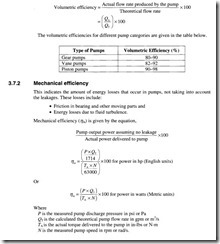
This indicates the amount of leakage, which takes place within the pump and involves considerations such as manufacturing tolerances and flexing of the pump casing.
Volumertic efficiency (T/v) is given by
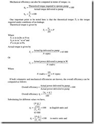
The actual power delivered to a pump from a prime mover through a rotating shaft is known as Brake power and the actual power delivered by a pump to a fluid is known as hydraulic power.
Pump capacity
Pump manufacturers usually specify pump performance characteristics in the form of graphs, for better visual interpretation. The variation in actual pump capacity depends mainly on the following three factors:
• Discharge pressure: The higher the discharge pressure, greater the internal leakage and hence lower is the actual capacity.
• Running clearances: Large clearances mean greater internal leakage.
• Oil viscosity: The use of low-viscosity oil leads to greater internal leakages.
To keep the design consideration common globally, all gear pumps are designed for their rated capacity at a certain constant pressure. When the pressure at the discharge of a pump increases, the flow rate of the pump reduces. Hence, while designing a pumping system, care should be taken to ensure that the discharge line offers the least resistance to pump discharge.
Effect of running clearance on capacity
Clearances exceeding specified tolerance levels tend to adversely affect the pump performance and efficiency through increased leakage. Let us analyze this further, specifically in relation to gear pumps, in order to examine how any dilution in running clearances ends up adversely affecting pump performance.
All gear pumps are manufactured precisely with specific minimum clearances as per design. However, it is not possible to actually have a zero clearance. Phenomena such as wear, scuffing, abrasive friction and rusting are said to be the major causes for increase in this clearance. It has been found that a 0.04 mm side clearance produces eight times as much internal leakage compared to a 0.02 mm side clearance.
A test was carried out wherein the running clearance on a 1500 rpm pump was intentionally varied, to determine its effect on the pump capacity. During the course of these tests the following findings were established.
A change in the side clearance from 0.025 to 0.045 mm resulted in a 20% reduction in the pump capacity. The pump capacity was found to reduce further with a decrease in pump speed from 1500 to 400 rpm, with the other conditions being held constant.
Effect of oil viscosity on capacity
If the viscosity of the oil is high, the pump capacity is found to increase and vice versa. Since the viscosity is a function of temperature, cold oil results in a higher capacity.
For a similar pump as used earlier and for the operating conditions listed below, the following observations were recorded.
(a) A 20 °C rise in oil temperature led to a decrease in pump capacity by 20%.
(b) Upon further lowering of the pump speed, the pump capacity was found to decrease further.
It is therefore clear that the pump capacity is closely related to the temperature of the oil being used. Hence, it is quite imperative for any testing procedure involving the determination of the pump internal condition or its capacity, to specify the oil temperature, which otherwise would render the whole exercise meaningless.
Pump performance curves
The performance characteristics of pumps are usually specified in the form of graphs. The test data obtained from actual performance tests carried out on pumps are graphically represented for better interpretation. We have seen above the effects of various changes on the capacity of a gear pump. Going further, let us now consider the case of a radial piston pump and study its performance characteristics as represented by the graphs shown in Figure 3.20 and depicting the following relationships.
• Change in discharge flow with change in pump speed
• Change in discharge flow with respect to discharge pressure
• Effect of change in speed on pump efficiency.
From the above graphs, the linear relationship between discharge flow and pump speed is established. As regards the relationship between pressure and discharge flow, it is found that the discharge flow is nearly constant over a wide range of pressure. The curves representing volumetric and overall efficiencies are based on a pump whose pressure rating is 2000 psi. Both the efficiencies are found to steadily increase with increase in pump speed before starting to decline at speeds beyond 2000 rpm.
Comparison of pump performance parameters
The table below compares various performance parameters such as pressure, speed, overall efficiency and flow for the various categories of hydraulic pumps.
Noise
Noise is another of the important parameters used to determine pump performance. It is measured in units of decibels (dB). Any increase in the noise level normally indicates increased wear and tear and imminent pump failure. Pumps are good generators but poor radiators of noise. However, the noise we hear from the pump in operation is not just the sound coming from the pump, but includes vibration and fluid pulsations as well. In general, fixed displacement pumps are less noisy than variable displacement pumps as they have a rigid construction.
Pump speed has a strong influence on its noise, while the pressure and size have about an equal or lesser effect. The following graph (Figure 3.21) shows these effects.
Another common cause for noise in hydraulic systems is the presence of entrapped air bubbles in the fluid. These air bubbles, even if they represent less than 1% by volume, change the compressibility of the fluid so much that they can sometimes cause even a fairly silent pump to operate with excessive noise. Entrapped air also leads to the phenomenon of cavitation in pumps about which we shall discuss in detail.
Cavitation in pumps
Pump cavitation is another phenomenon associated with noise and caused by the presence of entrained air bubbles in the hydraulic fluid or vaporization of the hydraulic fluid. It normally occurs when the pump suction lift is excessive and the pump inlet pressure falls below the vapor pressure of the fluid. As a consequence of this, the air bubbles that originate in the low-pressure inlet side of the pump collapse upon reaching the high-pressure discharge side, resulting in increased fluid velocity and giving rise to impact forces which can erode the pump components and shorten its life.
Following are a list of measures that can be undertaken to minimize the effect of cavitation:
(a) Maintaining short pump inlet lines
(b) Maintaining suction line velocities below 1.5 m/s (4.9 ft/s)
(c) Positioning of the pump as close to the reservoir as possible
(d) Minimizing the number of inlet line fittings
(e) Using low-pressure drop filters and strainers in the inlet side
(f) Using the proper oil as per the recommendations of the manufacturer.


