Conventional printing technologies
THIS CHAPTER DISCUSSES THE THREE CONVENTIONAL printing technologies: impact, thermal, and ink j et, as well as the construction and detailed operation of their print head mecha nisms (figure 3-1). These technologies are called “conventional” because their print heads are clearly defined devices, easy to rec ognize on sight, and easy to replace as an individual assembly. Electrophotographic (EP) printing is accomplished as a “process” of many interacting mechanisms, rather than the actions of any one device. This makes EP technology more complex and difficult to understand, so it is considered to be a “nonconventional” print ing method. EP printer technology is discussed in Chapter 4.
Impact printing
Impact printing is the oldest, simplest, and probably the most de pendable form of printing ever developed. Images are literally slammed against a page as a matrix of individual dots; the dot pat terns form letters and graphics. Impact printers are known collec tively as dot-matrix impact (DMI) printers. Figure 3-2 shows a comparison between character (e.g., typewriter) and dot-matrix print. Notice how the DMI figure appears rougher and less defined than its die counterpart.
The dot mechanics
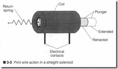
Each dot is generated by an individual metal print wire driven through a solenoid as illustrated by figure 3-3. When an electrical pulse reaches the solenoid, it energizes the coil and produces a brief, intense magnetic field. This field “shoots” its print wire against the page. After the pulse passes, the solenoid’s magnetic field col lapses. A return spring pulls the wire back to a rest position. In actual practice, DMI solenoids and print wires are very small as semblies. A typical print wire might only travel about 0.5 mm. This distance is known as wire stroke.
Not all DMI heads hold their print wire directly within the sole noid’s coil. While this approach might work well for smaller, gen eral-purpose heads, heavy-duty heads need larger coils than can be stacked vertically. Each solenoid is mounted offset from one another, then connected to their respective print wires using a mechanical linkage as shown in figure 3-4. Due to the additional mechanical components, heavy-duty print heads operate some what slower than “direct-drive” heads, and they usually do not last as long because of the additional mechanical wear.
Driving the dot
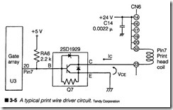
Solenoids require a substantial amount of electrical energy very quickly to develop a magnetic field strong enough to move a print wire. Figure 3-5 shows a driver circuit similar to one used in every day DMI printers. A plinter’s ECU produces a narrow logic pulse, which is sent along to a transistor driver. Infigure 3-5, a gate array ASIC (marked U3) is responsible for generating the logic signal. However, logic circuits alone cannot handle enough power to op erate a solenoid directly, so a transistor driver is used. A high power dJiver transistor (such as the 2SD1929) acts as a switch that turns the solenoid on and off. A driver voltage (typically 24 V,
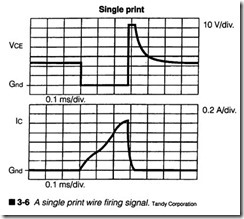
much higher than the +5-V logic supply voltage) provides the en ergy required. A relatively small nonpolarized capacitor (marked Cl4) provides supplemental power supply filtering. One such driver circuit is required for every print wire.To understand more about dynamics of the driver circuit, refer to the oscilloscope diagram of figure 3-6. The upper trace shows what happens to the transistor’s output voltage when a logic pulse
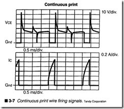
arrives. The lower trace illustrates the corresponding effects on solenoid current. As you can see, current is not instantaneous; there is a rapid period of ramp-up (about 0.3 ms or 300 J.LS), fol lowed by a sudden drop. The print wire will overcome the restric tion of its return spring and fire at roughly the current peak. You can see the effects of continuous print in figure 3-7.
Electrically speaking, solenoids are not very efficient devices. Only 1% or 2% of the energy provided is actually converted to force. The remaining energy is wasted as heat. Heating can have severe effects that include print wire jamming, coil burnout, and even a potential bum hazard. Solenoids usually require anywhere from + 12 to +24 Vde at currents greater than 1.5 A, so the “on time” for a typical solenoid must be kept very short (well below 0.5 ms, as in figure 3-6) to prevent excessive heating. Metal heat sinks are often die-cast into the head housing to dissipate excess heat as quickly as possible. Short pulses also allow extremely fast frring cycles, and most current DMI print heads can frre at greater than 300 Hz. Some models can be fired as fast as 600 Hz.
Dot specifications
DMI print heads use an array of 9 or 24 print wires arranged inver tical columns as shown in figure 3-8. There are three major me chanical specifications that you should be familiar with. Wire
diameter specifies the diameter of each print wire (normally ex pressed in millimeters). This tells you how large each dot will be. The distance between the center of each dot is known as wire pitch (also expressed in millimeters). Finally, the height of each fully formed character is specified (in millimeters) as character height (CH). Wrre diameter and pitch are much smaller for 24-pin heads than for 9-pin heads.
Not all wires can be used to form every character. For example, a 9-pin print head with a 2.5-mrn CH might only use seven wires to form most characters. Wires 8 and 9 could be used to form char acters with descenders. The concept of true descenders is illus trated in figure 3-9. When all nine wires are used to form characters, there is no room left for descenders, so characters can be printed with false descenders, also shown in figure 3-9. Overall character size might appear larger when all nine wires are used, but many people fmd false descenders awkward.
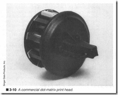
The technique of DMI printing is every bit as straightfonvard as character printing, but the actual formation of each letter, num ber, or symbol is a bit more involved. Data sent from a host com puter is interpreted by the print er’s main logic and converted to a series of vertical dot patterns. Motor commands start the carriage (and print head) moving across the platen. Simultaneously, printer circuits will send each dot pattern to the print head in se ries. Each dot pattern frres the corresponding print wires through an inked tibbon to leave a permanent mark on the page. This is also called serial or moving-head operation. Figure 3-10 is a photo of a heavy-duty DMI print head.
Early DMI printers lacked the dot resolution and electronic so phistication to produce letter-quality print as character printers could. Characters were printed uppercase in a 5 x 7 dot matrix. Such printing was clear and highly legible, but not visually pleas ing. Advances in electronics and printer communication allowed both upper- and lowercase characters to be printed , while im provements in materials and construction techniques resulted in smaller, more reliable print heads. This mad e DMI printing easier to look at, but still could not approach letter quality. With the in troduction and widespread acceptance of 9-pin print heads , en hanced features became possible.
The additional dots offered by a 9-pin head improved the appear ance of each character even more, and provided enough detail to make several different font styles practical, but individual dots were still visible. Near-letter quality (NLQ) was finally accom plished through multipass printing of the same line. Paper position is shifted just a fraction, then a subsequent series of dots would “fill-in” some of the spaces left by a previous pass. Forming a line of NLQ characters might take two, three, and four passes (de pending on the particular printer). A single pass per line became known as draft mode.
NLQ printing is limited by the printer’s speed. The more passes needed to form a line of print, the more time that is required. For example, suppose a single pass (draft) takes one second. If two passes are required for an NLQ line, print time would be twice as long (two seconds). If four passes are required, print time would be four times as long (four seconds). For long documents, this ad ditional time can really add up. As a general rule, you can save sub stantial time (and your ribbon) by using the draft mode until you are ready to print the fmal version of your document.It was not until the introduction of the 24-pin DMI print head that NLQ print could be accomplished in only one pass. ‘TWo vertical columns of 12 wires are offset from one another. As a 24-pin head moves across the page, the leading colunm places a first “pass” of dots. This forms a basic character image, which is already superior to the 9-pin equivalent. Immediately after the leading colunm fires, the lagging colmnn places a second “pass” of dots to fill in each charac ter. In this way, two passes are made effectively at the same time.
Advantages & disadvantages of DMI printing
To this day, DMI print heads remain a cornerstone of conunercial printing technology. They are flexible and inexpensive devices, ca pable of a wide variety of fonts and enhancements, as well as draft or NLQ performance and bit-mapped graphics. DMI heads are rea sonably fast, so they can achieve speeds easily exceeding 160 CPS. They are reliable devices. Heavy-duty print heads can last through more than 30 million characters. Smaller, general-purpose heads can last for more than 100 million characters. Impact printing is mandatory for printing multicopy forms. Finally, they require very little maintenance except for periodic routine cleaning.
However, impact printing is very noisy. The continuous drone of print wires striking paper can become quite annoying. Although DMI printers are now made with plastic coverings that baffle much of its noise, they do not quiet the printer completely. Limited dot resolution is another concern. You might not notice this for NLQ text, but you can see individual dots in draft or bit graphics modes. You can only achieve just so many dots per inch. Finally, head overheating can be a problem during long printouts, especially when printing graphics where many wires must flre repeatedly.
Thermal printing
Thermal printing technology eliminates the need for impact alto gether by using heat to form characters and graphic images on pa per. Instead of fomting dots through a matrix of electromechanical solenoids, thermal print heads employ an array of resistive semi conductor heating elements (called dot heaters). Electrical pulses from the printer’s driver circuits transfer energy to each desired dot heater causing them to heat up rapidly. This in turn will discolor the appropriate points on temperature-sensitive paper or a thermal transfer ribbon. Thermal dot-matrix (TOM) print heads are avail able in serial (moving head) and line-head versions, which can be chosen depending on the particular application. Before you learn about the operation of thermal printing in detail, however, you must understand the way in which TDM heads are constructed.
Thermal head fabrication
TDM heads are not built as an assembly of other parts the way other heads are. They contain no wires, solenoids, linkages, or other individual parts. Instead, they are fabricated much like an in tegrated circuit; one layer of material at a time is deposited onto previous layers in masked patterns that form resistive elements, their interconnections, electrical insulators, and protective coat ings. Three popular fabrication methods are discussed as follows.
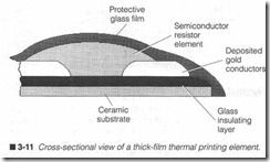
Thermal head thick-fllm fabrication is shown in figure 3-11. A semiconductor resistance element is deposited between two con ductors and covered with a protective glass film. Everything is fab ricated onto a ceramic substrate (or support structure) insulated by a glass insulating layer.
Thick-film technology can achieve resolutions of 12 dots per millimeter. Each dot heater exhibits a resistance that can range from 160 to 3,000 n depending on the number of dots and the print head’s intended application. Each dot is roughly round and faintly defined. The working temperature of each dot can easily exceed 350°C at the resistive element itself, yet typical thick-film heater elements will last for more than 30 million pulses, and they are
 highly resilient to power overload conditions. Line-print head ver sions are often manufactured using thick-film technology. Another issue to consider with TDM print heads is wear; after all, the print head must be in physical contact with the page surface (or ther mal transfer ribbon ). Over time, the friction encountered at the page surface will wear away the TDM head. Today, protective fllm coverings can endure mor e than 30 kilometers of wear against the page surface before failure.
Figures 3-12 and 3-13 illustrate typical thin-fllm fabrication tech nologies. Both figures are variants of the same approach. A ce ramic substrate and glass insulating layer form the foundation of a thin-film heater.Unlike the thick-fllm technique, a thin-film resis tor is much thinn er, and is fabricated underneath its electrical conductors. Finally, two separate protective layers are added.
Thin-fllm technology offers several performance differences versus thick-fllm devices. Thin-film devices can achieve resolutions as high as 16 dots per millimeter. Each dot heater can range from 1.5 to 50 ndepending on the number of dots and intended application of the head . Dots appear square and are sharply defined. Thin-film dot heaters can easily survive more than 50 million pulses , but they are not very tolerant of driver overloads. The hard tantalum covering can undergo more than 70 kilometers of surface wear, more than t\vice that of a thick-film covering. Thin-film technology can also be used to manufactur e either serial or line-print heads.
Although TDM heads are considered rugged and reliable devices, the hard glass and ceramic materials they contain are also very fragile. Impact or physical abuse can fracture the entire structure
and ruin the assembly. Because they are fabricated as a single as sembly, there are no serviceable parts inside. When one or more dot heaters fail, the whole TDM head must be replaced.
Contact pressur e is surprisingly important in thermal printing sys tems. The print head must present enough pressure to ensure good thermal transfer to its heat-sensitive paper or thermal rib bon , but not so much pressure where it interferes with the paper transport mechanism. Excessive pressure will also decrease the head’s wear resistance by breaking down its protective covering layer faster. As a general rule, contact force should be between 100 to 250 grams. When you examine thermal print heads closely, you might note that some of their faces have a slight curve to match the platen.
Serial head operation
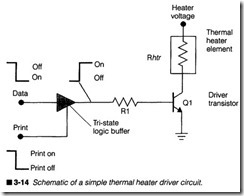
A thermal heater can be fired much the same way as an impact so lenoid as shown in figure 3-14. Data for such a dot driver circuit is applied to a tri-state buffer. Note the extra input marked “print.” This is an enable input that controls the tri-state buffer. While “print” is brought logic high, the buffer’s output state will equal its input state (i.e., a logic 1 input will yield a logic 1output, and vice versa). This enable line is very handy because it allows data to be set up in advance on any number of dot heaters. The “print” signal can then be strobed on all drivers simultaneously. For the simple driver circuit of figure 3-14, a logic 1 will fire a dot heater, and a logic 0 will not. Each dot heater will have its own driver circuit.
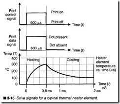
Timing is very important to the successful operation of a thermal print head as you can see in figure 3-15. A dot heater cannot work instantaneously; it takes a certain amount of time for it to reach a working temperature. It takes even more time for it to cool off be fore firing again. This entire cycle is called the pulse period (or SLT). When a dot heater is fired by a logic 1, it begins to heat. It
only takes a pulse width of about 0.6 to 1.0 milliseconds (ms) to reach a marking temperature of 350°C. For figure 3-15, 0.6 ms is used as an example. At that point, the heater has formed its dot and must be allowed to cool. Cooling can require more than 1.5ms in addition to heating time. If the head (or paper) moves before sufficient cooling can occur, printed dots will tend to appear “pulled” or smudged. Once the heater has cooled enough, it might be moved and fired again.
It is possible to coax even more heat from TOM heaters by length ening the driving pulse width. Because energy is applied for a longer time, heaters will reach higher temperatures. However, this must be matched by even longer cooling times. A ROHM NS0907- D1 thermal print head makes an excellent example. Suppose a pulse width of 1.0 ms requires a cool-down time of another 1.0 ms (SLT would be 2.0 ms). If pulse width were extended to 1.2 ms, SLT would have to be 4.0 ms to allow sufficient cooling time. A pulse width of 1.6 ms would require an SLT of 8.0 ms (a much longer cool-down time). It is helpful to understand the relation ship of time and temperature, but for the purposes of troubleshooting and repair, you should not be concerned with pulse width and SLT. Those values will be fixed by software in the printer’s ECU.
TDM print heads require much less operating power than DMJ de vices because only a small amount of current is needed to fire each dot heater. A typical impact solenoid might require a pulse of 1.8 A at 12 Vdc for proper firing. That equates to (1.8 Ax 12 Vdc]21.6 watts (y{) per solenoid. For a 9-pin printer, the power supply must be able to provide (21.6 W x 9] about 195 Wunder “worst case” conditions. Such a power demand makes DMI printers unsuitable for mobile or battery-powered operation. On the other hand , a typ ical TDM print head requires only about 2 W (or less) per dot. For a 9-pin serial TDM print head, it would take [2 W x 9] 18 W to fire al19 dot heaters together. As you might imagine, this represents a ten-ific power savings. Thermal printers are often found in mobile or battery-powered instrumentation.
Line head operation
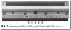
TDM line-print heads take a bit more complicated approach. In stead of assembling images as a series of vertical dots scanned from side to side, a line-print head uses a single horizontal row of dot heaters to assemble complete images as paper advances. Fig ure 3-16 illustrates a ROHM TDM line-print head. One dot heater is available for every possible point in a horizontal line.
Depending on the width of a head (which will probably be as wide as the pa per it is printing), there might be as few as 160 or as many as 7,000 dot heaters.
Because the print head now spans the entire page width, there is no longer any need for a carriage mechanism. Data is sent from the host computer and interpreted by the printer’s ECU one FULL line at a time, then translated into a series of horizontal dot patterns. In this way, the line head forms entire lines one horizontal row at a time (as opposed to serial heads that form lines as one vertical column at a time). Line-print heads are available for use with heat sensitive paper or thermal transfer applications.
Sending the actual print data to a line-print head, however, is a more complex and involved process than for a serial head. After all, nine discrete driver circuits to fire a serial print head (one driver for each dot heater) are simple enough to follow and trou bleshoot, but when you deal with a line-print head that can contain thousands of dot heaters, discrete drivers are totally inadequate. In response to this, TDM line head manufacturers take advantage of sophisticated VLSI 0/ery Large-Scale Integration) technology to fabricate data handling and dot driver circuitry right onto the print head assembly itself. Figure 3-17 shows a simplified internal dia gram for a typical line-print head.After the printer’s ECU translates a line of characters into rows of horizontal dots, data for each row is sent in series (one bit at a time) into the DI input of the line head. Remember that data is made up of digital logic conditions corresponding to a heater’s out put; a logic 1 is on and a logic 0 is off. When a complete row of data is fed into the print head, the dot heaters can be fired to produce a row of finished print. Ideally, all dot heaters should be able to fire together; it would print one full row at a time. Unfortunately, the cumulative current required by every heater firing together would put a strain on even the best power supply. It would also create a strong heat surge. For the example head of figure 3-17, each of the 2,048 dot heaters need 0.19 W (190 mW) of power. If every dot fires together, the head will dissipate a stunning [0.19 W x 2,048] 389 W! A 24-V power supply would have to provide [389 W I 24 Vdc] about 16 A.
In order to limit line head power dissipation, power surges are lim ited by firing the line-print head in segments. The 2,048 dots of fig ure 3-17 are divided into four segments of 512 dots. A segment is enabled using the trigger (or “strobe”) lines (marked STR1 through STR4). There might be as many as four or more strobe lines de pending on the density of the particular head. One segment of 512 dots firing simultaneously would dissipate [0.19 W x 512] about 98 W; a much more manageable power requirement for a power sup ply. It will take four times longer to print with this “segmented” ap proach, but it places much less stress on printer electronics, and allows extra cooling time for unused segments.
Thermal printing media
Heat generated by each dot must be transferred to a page surface as required in order to form permanent images. This is accom plished in either of two ways: direct contact or thermal transfer. As the name implies, direct contact requires that a print head be in direct contact with the paper surface. Heat is used to activate heat-sensitive chemicals in the paper, which cause those points to discolor and leave permanent marks. Most heat-sensitive papers generate either blue or black marks.
This offers a simple, reliable printing approach, but it is not with out its disadvantages. Perhaps the most notable disadvantage is that standard paper (such as 20-lb bond xerography-grade paper) cannot be used. Temperatures developed by a thermal print head are insufficient to cause discoloration on normal paper without burning it. Heat-sensitive chemicals cause thermal paper to dis color at much lower temperatures. Such sensitized paper is usu ally delicate and sensitive material. It only has a limited shelf life (typically a few years). Age, sunlight, humidity, and a variety of chemical vapors will ruin the paper. Finally, thermal paper is man ufactured on long, continuous rolls. Its tendency to curl makes it difficult to handle.
Thermal transfer uses heat generated by each dot to deposit solid ink onto a page surface. A narrow plastic ribbon is coated with a heat-sensitive solid ink made of waxes, oils, and dies. By altering the ratio of these materials, ink viscosity and melting point can be optimized to suit a print head. As with DMI print heads, ribbons are inserted between the print head and paper. When dot heaters fire, they melt corresponding points of plastic ink, which remain on the paper to form images. Because it is an ink ribbon (not the paper) that must be heated, thermal transfer printing will work with just about any kind of smooth, standard-bond paper. Print color is determined by the color of the plastic ink. TDM print heads used for thermal transfer printing require slightly more power than direct contact heads in order to melt plastic ink reliably.
Advantages & disadvantages of TDM printing
Thermal dot-matrix technology enjoys several advantages over other printing methods. First, TDM is very quiet. Even though contact is required, there are no moving parts to generate noise. Power consumption is also very low in TDM heads. Thermal dot heaters in serial heads often require less than 2 W per dot. Line print heads need even less (in the range of 0.2 W per dot). Com pare this to a DMI head that usually takes more than 12 W per solenoid. Low power consumption makes TDM heads ideal for mobile and battery-powered applications. TDM heads are simple and reliable devices. They are totally self-contained; there are no moving parts or apertures that can jam or clog. About the only preventive maintenance required for TDM heads is an occasional wipe-down to remove accumulations of dust and dirt. Line-print heads simplify the printer by eliminating the need for a carriage mechanism. They also incorporate on-board circuitry for data han dling and dot driving. This too can greatly simplify the printer’s corresponding ECU. Print is clear and crisp, with resolutions that can rival that of an electrophotographic printer.
TDM print heads have a few disadvantages. Print time is slightly slower than other printing methods because of cooling time added to each printing cycle. This is just a slight difference. Thermal head life is shorter than most DMI heads, largely due to the sur face wear caused by paper friction. TDM heads are usually good for 10 million characters or less, where DMI heads can support 50 million characters or more. Finally, TDM heads cannot be ser viced; if a dot heater burns out or its internal circuitry fails, the en tire head assembly must be replaced.
Ink jet printing
While impact and thermal technologies require a print head to ac tually contact the page surface in order to print, ink jet dot-matrix printing is a “noncontact” technology; that is, ink jet heads never come into contact with the printing surface. Instead, liquid ink is literally spray-painted onto a page. Conunercial ink jet printers use one of two approaches to spray ink: drop-on-demand, and in termittent jet. These techniques are both very similar. The drop on-demand technique requires an individual command for every dot that is ejected from an ink jet print head, much like DMI print wires that are fired by discrete pulses. The intermittent jet ap proach fires streams of ink (a continuous series of dots) rather than individual dots. By timing the start and duration of each ink stream very precisely, it is possible to achieve extremely fme detail at resolutions that are now exceeding 360 x 360 dpi. For the pur poses of this book, ink jet print heads are assumed to use inter mittent jet technology.
Inside the ink jet print head
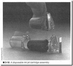
When compared to other types of print heads, ink jet heads are perhaps the simplest and most straightforward design. The ink reservoir is provided in a prepackaged container. The ink con tainer might come in a replaceable cassette, or it might be inte grated into a throw-away print head assembly. When the ink is installed, gravity and capillary action feed the ink along narrow channels, and the ink comes to rest at each nozzle, the exit aper ture, where the ink is ejected. There might be 12, 24, 50, or more depending on the vintage and complexity of the particular ink jet head. The nozzles themselves are really nothing more than fme holes (each about the diameter of a human hair) drilled into a metal plate with a laser. You might wonder how liquid will stay at the nozzles without spilling out all over the place. The answer is that the ink’s viscosity and surface tension hold the ink in place until it is pumped out. Figure 3-18 shows you the internal compo nents of a throw-away ink jet print head.
Finally, every ink channel is fitted with an ink pump. In actual practice, an ink pump is almost microscopic, but it is the key ele ment in any ink jet head. Because each pump requires electrical pulses in order to run, a series of contacts will run to a connector on the print head. Like other dot-matrix technologies, each ink pump can be fired independently for maximum flexibility inimage formation. The circuitry needed to time and fire the ink pumps is
contained in the printer’s ECU, or on a supplemental driver board located close to the carriage transport system. There are two basic types of ink pumps: piezoelectric and bubble.
Piezoelectric pumps
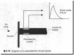
Ina piezoelectric pump, a ring of piezoelectr ic ceramic material is built into an ink channel as in figure 3-19. When a high-energy electrical pulse is applied across the ceramic ring, its piezoelectric quality causes it to constrict the channel. This causes a sudden displacement of volume that pushes out a single droplet of ink. Af ter the electrical driver pulse passes, ceramic returns to its origi nal shape, and more ink is drawn into the channel to make up the expelled droplet. Piezoelectric ceramic requires short pulses (in the 5- to 10-J..ls range) at high energy levels. Pulse amplitudes can be anywhere from 70 to 200 V depending on the particular design of the channel and the type of ceramic used. One pump is required pe r channel, and can fire at rates approaching 5 kHz (5,000 dots per second). This is one droplet every 200 J..LS.
Bubble pumps
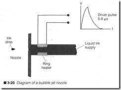
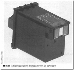
Bubble pumps (used in “thermal ink jet” or “bubble jet” printers) are also widely used to generate ink droplets; they are now perhaps the single most popular technology for disposable ink jet print heads. As you see in figure 3-20, nozzles and channel con struction are very similar to piezoelectric heads, but ceramic rings are replaced by ring heaters. An electrical driver pulse fires a ring heater. In turn, this heats ink in the immediate vicinity. As ink heats, a bubble forms and expands in the chann el. When the bub ble fmally bursts, its force ejects an ink droplet, and more ink is drawn in to fill the void. Heated ink droplets also dry faster on pa per. Although bubble pumps are fast-working devices, they are limited to firing rates of 1,000 dots per second. Ring heat ers (like the dot heaters found in thermal print heads) require a finite amount of time to cool after firing. If there is not enough cooling time, ink might actually dry out and clog inside the channel. How ever, bubble pumps do not require nearly as much energy to oper ate. Early units typically used 24- to 50-V pulses, but the new generation of mobile lap-top bubble jet printers uses even lower signals. You can see the proliferation of nozzles and electrical con tacts in the HP ink jet print head of figure 3-21.
Monochrome vs. color
Because the color of an ink jet’s output depends entirely on the color of its ink, the ink jet print er has become a preeminent plat form for low-cost, high-quali ty color printing . The principles in volved in a color ink jet design are virtually identical to those of monochrom e printers, but where a monochrome printer merely prints black and white (the presence or absence of dots), a color printer must interpret the colors of each dot, and provide a more sophisticat ed signal stream that will not only drive the print head, but will drive the proper color nozzles.
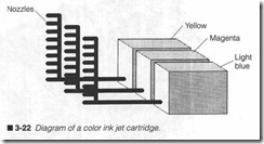
This marginal increase in complexity also demand s a slightly more complex print head as shown in figure 3-22. Essentially, a color ink jet head can have three or four separate ink systems integrated into the same head; three to handle the three key colors (yellow, magenta, and light blue), and a fourth color (black) might be in cluded. As you might imagine, crarruning three or four ink systems into a single print h ead is no small feat, and each ink reservoir is considerably smaller than the single-reservoir (monochrome) mod els; thus, color print heads have a much shorter life than mono chrome print heads.
Ink considerations
The kind of ink used in ink jet printers is typically an indelible, sol vent-based chemical that is resistant to drying in air. As a result , most ink jet heads can be left unattended for prolonged periods of time (often several days to several weeks) without fear of nozzle clogs due to drying. Most ink j et printers also have a type of “ink cap” sponge in the printer’s carriage horne position that wipes each nozzle whenever the head reaches its home position, and covers them whenever the printer is turned off. This can be an important factor in older ink jet printers because sponges become dried and hardened with ink (as well as age), so they are less effective at keeping the print head clean. Cleaning sponge replacement should be a routine procedure when servicing older ink jet printers.
Sooner or later, solvent will evaporate into the air. Evaporation be gins to increase the ink viscosity inside each channel; it becomes thicker. In early stages, this can cause ink to sputter or travel off course to the page. In advanced stages, solvent might evaporate entirely, or enough to allow ink to dry and harden in the channel. This is a clog. The afflicted nozzle(s) might still fire electrically, but no ink will flow until the clog is cleared. The ink jet head will have to be cleaned or purged. Clogs might also be dislodged through normal use. Once any viscous ink is forced out through normal use, proper operation will return automatically. Of course, disposable ink jet print heads (which do not support purging) can simply be replaced.
Recycling considerations
One of the side effects of disposable ink cartridges or ink jet print heads is that a huge amount of waste material is generated. When coupled with the relatively high cost of original manufacturer’s ink cartridges, the expended ink units open a wide market for recy cling. If you stroll through your favorite computer store, you will probably notice “ink cartridge refill kits” sitting near the ink car tridges, so the drive to recycle has made it to the retail level. Un fortunately, the refill kits are not compatible with all print heads, are not much less expensive than new print cartridges, and gener ate just about as much waste material as throwing the old ink car tridge/print head away. Chapter 7 discusses ink jet recycling in more detail, but if you plan to handle recycling on a regular basis, be sure to obtain the proper tools and materials for the job, prefer ably not from retail vendors. If you do not have the inclination to recycle ink jet cartridges yourself, there are a number of compa nies that accept and rework cartridges as a specialty.
Paper considerations
When ink droplets leave a nozzle, they are still in a liquid form. Once a droplet reaches paper, it must dry almost immediately so that the finished page can be handled. This is not always easy to accomplish if you are using the wrong paper type. Paper must accept ink into its fibers just the right way to dry it quickly, yet leave droplets on the surface for a crisp image. If paper absorbs ink too readily, the dried image might appear light or faint (lacking con trast). This is a typical problem with standard-weight xerography grade paper. If paper does not absorb ink quickly enough, ink might remain a liquid, which can smear and smudge when touched. Al though this is less common, gloss or specially coated papers might act this way.
To guarantee just the right drying characteristics, there is a spe cially made ink jet paper impregnated with clay or solvent-absorb ing chemicals that cause ink to dry quickly while leaving a clear, dark image. The best way to determine the compatibility between paper and ink is to test the printer in actual operation. Either ink or paper (usually the paper) might have to be changed to optimize the printer’s performance.
Advantages & disadvantages of ink jet printing
Ink jet dot-matrix technology offers a method of “noncontact” printing that can mark a wide variety of surfaces and paper types. Printing speeds rival any DMI printer, yet operation is very quiet. Nozzles and ink channels are incredibly small, so dot resolution can be extremely high (the head in figure 3-21 is used in a 300 x 300 dpi ink jet printer). Ink jet heads have no mechanical parts, so they are exceptionally inexpensive to manufacture, enjoy high re liability, and a long working life-some piezoelectric heads are rated for more than 1 billion dots. The low power requirements have made ink jet technology the forerunner of mobile, battery powered printers.
Unfortunately, ink jet heads are sealed devices. If one ink pump fails, the entire head must be replaced. Costs can also add up; even though ink cartridges can be made inexpensively, they can still be expensive items by the time they reach store shelves. Given the fairly limited number of pages handled by a single ink cartridge, the per-page cost of ink jet printing can still be high. The ink itself can be a frustrating problem. Ruptured print heads or leaking car tridges can spill thick, indelible ink everywhere. Fabrics and other porous materials are particularly susceptible to permanent stains; even your skin can be stained. While contemporary commercial “disposable head” printers have become very clean, there is still a risk of ink spillage.


