Electronic Timers
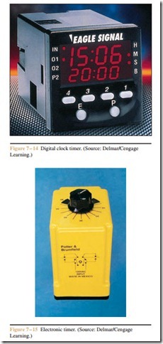
Electronic timers use solid-state components to provide the time delay desired. Some of these timers use an RC time constant to obtain the time base and others use quartz clocks as the time base (Figure 7 – 14). RC time constants are inexpensive and have good repeat times. The quartz timers, however, are extremely accurate and can often be set for 0.1 second times. These timers are generally housed in a plastic case and are designed to be plugged into some type of socket. An electronic timer that is designed to be plugged into a standard eight-pin tube socket is shown in Figure 7 – 15. The length of the time delay can be set by adjusting the control knob shown on top of the timer.
Eight-pin electron timers similar to the one shown in Figure 7 – 15 are intended to be used as on-delay
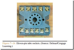
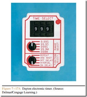
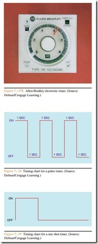
timers only. Many electronic timers are designed to plug into an eleven-pin tube socket (Figure 7 – 16) and are more flexible. Two such timers are shown in Figure 7 – 17A and Figure 7 – 17B. Either of these timers can be used as an on-delay timer, an off-delay timer, a pulse timer, or as a one-shot timer. Pulse timers continually turn on and off at regular intervals. A timing period chart for a pulse timer set for a delay of 1 second is shown in Figure 7 – 18. A one-shot timer will operate for one time period only. A timing period chart for a one shot timer set for 2 seconds is shown in Figure 7 – 19.
Most electronic timers can be set for a wide range of times. The timer shown in Figure 7 – 17A uses a thumbwheel switch to enter the timer setting. The top selector switch can be used to set the full range value from 9.99 seconds to 999 minutes. This timer has a range from 0.01 second to 999 minutes (16 hrs. 39 min.). The timer shown in Figure 7 – 17B can be set for a range of 0.01 second to 100 hours by adjusting the range and units settings on the front of the timer. Most electronic timers have similar capabilities.
Connecting Eleven-Pin Timers
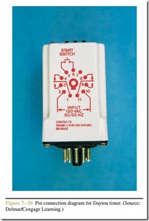
Connecting eleven-pin timers into a circuit is gen- erally a little more involved than simply connecting the coil to power. The manufacturer’s instructions should always be consulted before trying to connect one of these timers. Although most electronic timers are sim- ilar in how they are connected, there are differences. The pin connection diagram for the timer shown in Figure 7– 17A is shown in Figure 7– 20. Notice that a normally open push-button switch is shown across ter- minals 5 and 6. This switch is used to start the action of the timer when it is set to function as an off-delay timer or as a one-shot timer. The reason for this is that when the timer is to function as an off-delay timer, power must be applied to the timer at all times to permit the internal timing circuit to operate. If power is removed, the internal timer cannot function. The start switch is actually used to initiate the operation of the timer when it is set to function in the off-delay mode. Recall the logic of an off-delay timer: When the coil is energized,
the contacts change position immediately. When the coil is de-energized, the contacts delay returning to their normal position. According to the pin chart shown in Figure 7 – 20, pins 2 and 10 connect to the coil of the timer. To use this timer in the off-delay mode, power must be connected to pins 2 and 10 at all times. Short- ing pins 5 and 6 together causes the timed contacts to change position immediately. When the short circuit between pins 5 and 6 is removed, the time sequence be- gins. At the end of the preset time period, the contacts will return to their normal position.
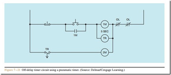
If electronic off-delay timers are to replace pneumatic off-delay timers in a control circuit, it is generally necessary to modify the circuit. For example, in the circuit shown in Figure 7 – 21, it is assumed that starters 1M and 2M control the operation of two motors, and timer TR is a pneumatic off-delay timer. When the start button is pressed, two motors start at the same time. The motors will continue to operate until the stop button is pressed, which causes motor #1 to stop running immediately. Motor #2, however, will continue to run for a period of 5 seconds before stopping.
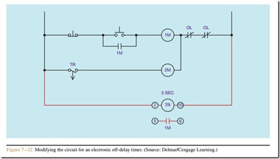
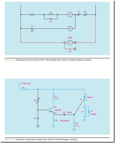
Now assume that the pneumatic off-delay timer is to be replaced with an electronic off-delay timer (Figure 7 – 22). In this circuit, notice that the coil of the timer is connected directly across the incoming power, which permits it to remain energized at all times. In the circuit shown in Figure 7 – 21, the timer actually operates with starter 1M. When coil 1M energizes, timer TR energizes at the same time. When coil 1M de-energizes, timer TR de-energizes also. For this reason, a normally open auxiliary contact on starter 1M will be used to control the operation of the electronic off-delay timer. In the circuit shown in Figure 7 – 22 a set of normally open 1M contacts is connected to pins 5 and 6 of the timer. When coil 1M energizes, contact 1M closes and shorts pins 5 and 6, causing the normally open TR contacts to close and energize starter coil 2M. When coil 1M is de-energized, the contacts reopen and timer TR begins timing. After 5 seconds, contacts TR reopen and de-energize starter coil 2M.
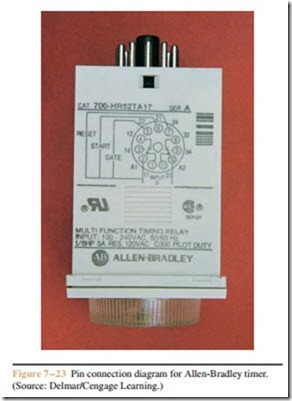
All electronic timers are similar, but there are generally differences in how they are to be connected. The connection diagram for the timer shown in Fig- ure 7 – 17B is shown in Figure 7 – 23. Notice that this timer contains RESET, START, and GATE pins. Connecting pin 2 to pin 5 activates the GATE function, which interrupts or suspends the operation of the inter- nal clock. Connecting pin 2 to pin 6 activates the START function, which operates in the same manner as the timer shown in Figure 7 – 17A. Connecting pin 2 to pin 5 activates the RESET function, which resets the internal clock to zero. If this timer were to be used in the circuit shown in Figure 7 – 22, it would have to be modified as shown in Figure 7 – 24 by connecting the 1M normally open contact to pins 2 and 6 instead of pins 5 and 6.
Construction of a Simple Electronic Timer
The schematic for a simple on-delay timer is shown in Figure 7– 25. The timer operates as follows: When switch S1 is closed, current flows through resistor RT
and begins charging capacitor C1. When capacitor C1 has been charged to the trigger value of the unijunction transistor, the UJT turns on and discharges capacitor C1 through resistor R2 to ground. The sudden discharge of capacitor C1 causes a spike voltage to appear across resistor R2. This voltage spike travels through capacitor C2 and fires the gate of the silicon-controlled rectifier (SCR). When the SCR turns on, current is pro- vided to the coil of relay K1.
Resistor R1 limits the current flow through the UJT. Resistor R3 is used to keep the SCR turned off until the UJT provides the pulse to fire the gate. Diode D1 is used to protect the circuit from the spike voltage produced by the collapsing magnetic field around coil K1 when the current is turned off.
By adjusting resistor RT, capacitor C1 can be charged at different rates. In this manner, the relay can be adjusted for time. Once the SCR has turned on, it will remain on until switch S1 is opened.
Programmable controllers, which will be discussed in Chapters 53 through 55, contain “internal” electronic timers. Most programmable controllers (PLCs) use a quartz-operated clock as the time base. When the controller is programmed, the timers can be set in time increments of 0.1 second. This, of course, provides very accurate time delays for the controller.
Review Questions
1. What are the two basic classifications of timers?
2. Explain the operation of an on-delay relay.
3. Explain the operation of an off-delay relay.
4. What are instantaneous contacts?
5. How are pneumatic timers adjusted?
6. Name two methods used by electronic timers to obtain their time base.
