Installations and commissioning
General installation guidelines
Environmental requirements
Modern power electronic AC VVVF converters, which are used for the speed control of electric motors, are usually supplied as stand-alone units in one of the following configurations. The first two are the most common configurations:
• IP00 rating: Designed for chassis mounting into the user’s own enclosure, usually as part of a MCC.
• IP20/IP30 rating: Designed for mounting within a ‘clean environment’, such as a weatherproof, air-conditioned equipment room. The environment should be free of dust, moisture, and contaminants. The temperature should be kept within specified limits.
• IP54 rating: Designed for mounting outside in a partially sheltered environment, which may be dusty and/or wet.
Environmental conditions for installation
The main advantage of an AC VSD is that the TEFC squirrel-cage motor is inherently well protected from poor environmental conditions and is usually rated at IP54 or better. It can be reliably used in dusty and wet environments.
On the other hand, the AC converter is far more sensitive to its environment and should be located in an environment that is protected from the following factors:
• Dust and other abrasive materials
• Corrosive gases and liquids
• Flammable gases and liquids
• High levels of atmospheric moisture.
When installing an AC converter, the following environmental limits should be considered:
• Specified ambient temperature: ≤40 ºC
• Specified altitude: ≤1000 m above sea level
• Relative humidity: ≤95%.
De-rating for high temperature
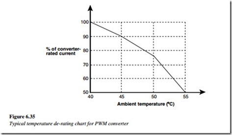
In regions or environments where there is a high ambient temperature, exceeding the accepted 40 ºC specified in the standards, both the motor and the converter need to be de-rated. This means that they can only be run, at loads that are less than their 40 ºC rating, to avoid thermal damage to the insulation materials.
The manufacturers of AC converters usually provide de-rating tables, for high temperature environments that are above 40 ºC. The typical graph in Figure 6.35 is for a modern PWM converter. This table should be used as a guide only and should NOT be taken to apply to AC converters in general, or to any converter in particular. The design of AC converters differs from manufacturer to manufacturer. The cooling requirements are never the same. The cooling requirements, of different models, from the same manufacturer may also be different.
De-rating for high altitude
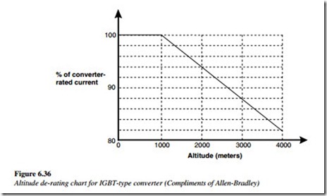
At high altitudes, the cooling of electrical equipment is degraded, by the reduced ability of the rarified atmosphere, to remove heat from the motor or the heat sink of the converter. The reason is because the air pressure falls with an increased altitude, air density falls, and consequently, its thermal capacity is reduced. In accordance with the standards, AC converters are rated for altitudes up to 1000 m above sea level. The rated output should be de-rated for altitudes above that.
The manufacturers of AC converters usually provide the de-rating tables for altitudes higher than 1000 m. A typical table is given in Figure 6.36, for a modern IGBT-type
AC converter. This table is NOT applicable to all AC converters. The de-rating of converters with high losses, such as those using BJTs or GTOs, will be much higher, than the de-rating required for low-loss IGBT or MOSFET converters. The high efficiency of the latter requires less cooling and it is less affected by altitude changes.
Mounting and enclosures for AC converters
If environmental conditions are likely to exceed these accepted working ranges, then arrangements should be made to provide additional cooling and/or environmental protection for the AC converter. The temperature limits of an AC converter are far more critical than those required for an electric motor. The temperature de-rating needs to be strictly applied. However, it is unlikely that a modern PWM converter will be destroyed if the temperature limits are exceeded. Modern AC converters have built-in thermal protection, usually a silicon junction device, mounted on the heat sink. The main problem of overtemperature tripping is associated with nuisance tripping and the associated downtime.
Although the efficiency of modern AC converters is high, typically ±97%, they all generate a small amount of heat, mainly due to the commutation losses in the power electronic circuits. The level of losses depends on the design of the converter, the PWM switching frequency and the overall power rating. Manufacturers provide figures for the losses (Watts) when the converter is running at a full load. Adequate provision should be made to dissipate this heat into the external environment and to avoid the temperature inside the converter enclosure rising to unacceptably high levels.
Converters are air-cooled either by convection (small power ratings) or assisted by cooling fans on larger power ratings. Any obstruction to the cooling air intake and from
the exhaust vents will reduce the efficiency of the cooling. The volume of air required for
cooling and the power loss dissipation determines the air-conditioning requirements for the equipment room.
The cooling is also dependent on there being a temperature differential between the heat sink and the cooling air. The higher the ambient temperature, the less effective is the cooling. Both the AC converter and the motor are rated for operation in an environment where the temperature does not exceed 40 ºC. When AC converters are mounted inside enclosures, care should be taken to ensure that the air temperature inside the enclosure remains within the specified temperature limits. If not, the converters should be de-rated in accordance to the manufacturer’s derating tables.
In an environment where condensation is likely to occur, during the periods when the drive is not in use, anti-condensation heaters can be installed inside the enclosure. The control circuit should be designed to switch the heater on when the drive is de-energized.
The heater maintains a warm dry environment inside the enclosure and avoids moisture being drawn into the enclosure when the converter is switched off and cools down.
AC converters are usually designed for mounting in a vertical position, to assist convectional cooling. On larger VSDs, cooling is assisted by one or more fans mounted at the bottom or top of the heat sink.
Many modern converters allow the following two alternative mounting arrangements:
• Surface mounting: The back plane of the converter is mounted onto a vertical surface, such as the back of an enclosure.
• Recessed mounting: The heat sinks on the back of the converter, projects through the back of the enclosure, into a cooling duct, and this allows the heat to be more effectively dissipated.
A sufficient separation from other equipments is necessary, to permit the unrestricted flow of cooling air through the heat sinks and across the electronic control cards. A general rule of thumb is that a free space of 100 mm should be allowed around all sides of the VSD. When more than one VSD is located in the same enclosure, they should preferably be mounted side by side rather than one above the other. Care should also be taken to avoid locating temperature-sensitive equipment, such as thermal overloads, immediately above the cooling air path of the VSD.
Adequate provision must be made to dissipate the converter losses into the external environment. The temperature rise inside the enclosure must be kept below the maximum-rated temperature of the converter.
General safety recommendations
The manufacturer’s recommendations for installation should be carefully followed and implemented. The voltages present in power supply cables motor cables, and other power terminations are capable of causing a severe electrical shock.
In particular, the local requirements for safety, which are usually outlined in the wiring rules and other codes of practice, should always take priority over the manufacturer’s recommendations. The recommended safety earthing connections should always be carefully installed, before any power is connected to the VSD equipment. AC VSDs have large capacitors connected across the DC link, as described in Chapter 3. After a VSD is switched off, a period of several minutes must be allowed to elapse before any work commences on the equipment. This is necessary to allow these internal capacitors to discharge fully. Most modern converters include some form of visual indication when the capacitors are charged.
Hazardous areas
In general, power electronic converters should not be mounted in ‘hazardous areas’, even when connected to an ex-rated motor, as this may invalidate the certification. When necessary, converters may be mounted in an approved enclosure and certification should be obtained for the entire VSD system, including both the converter and the motor.

