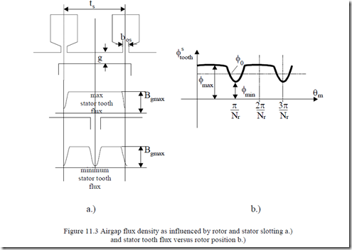
As already documented in the previous paragraph, the stator (and rotor) slot openings produce variation in the airgap flux density distribution (Figure 11.3).
In essence, the total flux in a stator and rotor tooth varies with rotor position due to stator and rotor slot openings only in the case where the number of stator and rotor slots are different from each other. This is, however, the case, as Ns ≠ Nr at least to avoid large synchronous parasitic torques at zero speed (as demonstrated in Chapter 10).
The stator tooth flux pulsates due to rotor slot openings with the frequency fPS = N fr (1p−1S) = Nr pf1 , for S = 0 (no-load). The flux variation coefficient Kφ is
Kφ = φmax2φ− φ0 min (11.26)
The coefficient Kφ, as derived when the Carter coefficient was calculated in [6]
γ2g (11.27)
Kφ =
2ts
with γ2 as
bor 2
γ2 = gbor (11.28)
5 +
g
Now, by denoting the average flux density in a stator tooth with Bots, the
|
flux density pulsation Bp1 in the stator tooth is |
|
|
γ BPs = Bots 22tgs |
(11.29) |
|
(11.30) |
Bg0–airgap flux density fundamental.
We are now in the classical case of an iron region with an a.c. magnetic flux density BPs, at frequency fPs = Nrf/p1. As Nrf/p1 is a rather high frequency, eddy current losses prevail, so
PPs0 = Cep B1Ps 2 f50Ps 2Gsteeth; Gsteeth −stator teeth weight (11.29)
In (11.31), Cep represents the core losses at 1T and 50Hz. It could have been for 1T and 60 Hz as well.
Intuitively, the magnetic saturation of main flux path places the pulsation flux on a local hysteresis loop with lower (differential) permeability, so saturation is expected to reduce the flux pulsation in the teeth. However, Equation (11.31) proves satisfactory even in the presence of saturation. Similar tooth flux pulsation core losses occur in the rotor due to stator slotting. Similar formulas as above are valid.
![]() PPr0 = Cep B1Pr 2 f50Pr 2 Gteeth ; fpr = Ns pf1 γ1g ; Botr = Bg0 tr −trbor (11.32)
PPr0 = Cep B1Pr 2 f50Pr 2 Gteeth ; fpr = Ns pf1 γ1g ; Botr = Bg0 tr −trbor (11.32)
BPr = Botr 2tr
bos 2
γ =1 gbos
5+
g
As expected, Cep – power losses per Kg at 1T and 50 Hz slightly changes when the frequency increases, as it does at Ns pf1 or Nr pf1 . Cep = CeK, with K
= 1.1 – 1.2 as an empirical coefficient.
Example 11.2
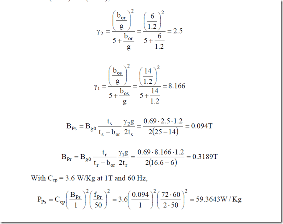
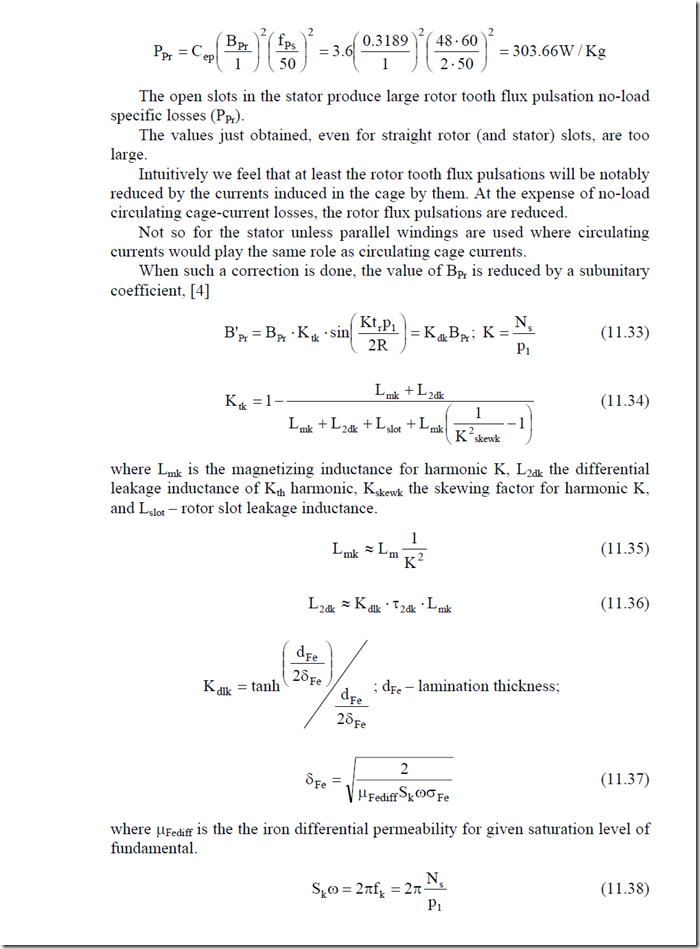
For the motor in Example 10.1, let us calculate the tooth flux pulsation losses per Kg of teeth in the stator and rotor.
Solution
In essence, we have to determine the flux density pulsations BPs, BPr, then fPs, fPr and apply Equation (11.31). From (11.26) and (11.32),
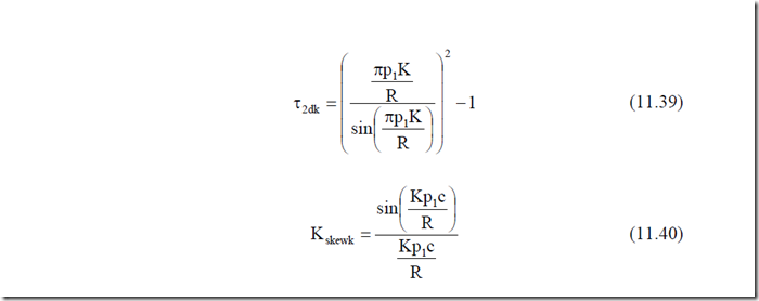
Skewing is reducing the cage circulating current reaction which increases the value of Ktk and, consequently, the teeth flux pulsation core losses stay undamped.
Typical values for Kdk–the total damping factor due to cage circulating currents–would be in the range Kdk = 1 to 0.05, depending on rotor number slots, skewing, etc.
A skewing of one stator slot pitch is said to reduce the circulating cage reaction to almost zero (Kdk ≈ 1), so the rotor tooth flux pulsation losses stay high. For straight rotor slots with Kdk ≈ 0.1 – 0.2, the rotor tooth flux pulsation core losses are reduced to small relative values, but still have to be checked.
11.3.3. No-load tooth flux pulsation cage losses
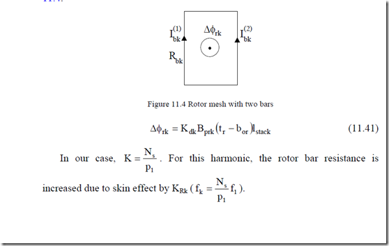
Now that the rotor tooth flux pulsation, as attenuated by the corresponding induced bar currents, is known, we may consider the rotor bar mesh in Figure
11.4.
increased due to skin effect by KRk (fk = Np1s f1 ).
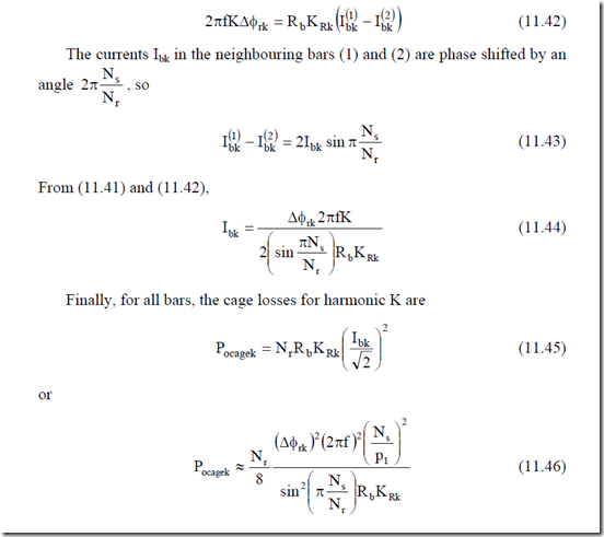
The skin effect in the end ring is much smaller, so the ring resistance may be neglected. If we also neglect the leakage reactance in comparison with rotor bar resistance, the equation of the mesh circuit in Figure 11.4 becomes
Expression (11.46) is valid for straight rotor slots. In a skewed rotor, the rotor tooth flux pulsation is reduced (per stack length) and, thus, the corresponding no-load cage losses are also reduced. They should tend to zero for one stator slot pitch skewing.
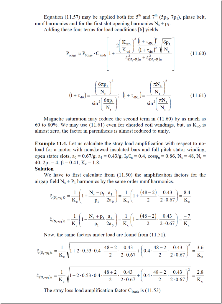
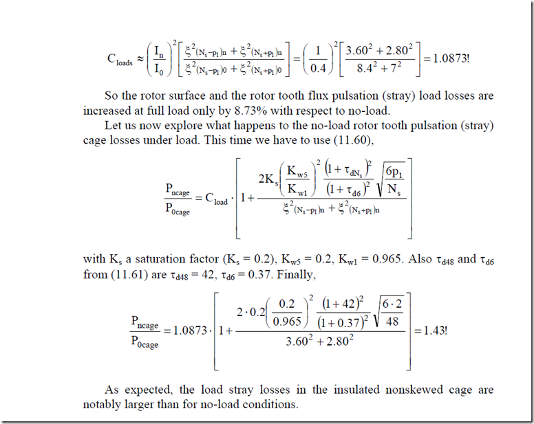
Example 11.3. Consider the motor in Example 11.1, 11.2 with the stack length lstack = 0.4 m, rotor bar class section Abar = 250 mm2, (Ns = 48, Nr = 72, 2p1 = 4).
The rotor bar skin effect coefficient for fk ![]() Hz is KRk =
Hz is KRk =
15. Let us calculate the cage losses due to rotor tooth flux pulsations if the attenuating factor of Kdk = 0.05.
Solution
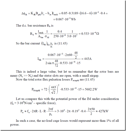
With Kdk = 0.05 and Bpr = 0.3189, from Example 11.2 we may calculate ∆φk (from 11.41).
∆φrk = K Bdk prk (tr − bor )lstack = 0.05⋅−0.3189 16⋅( .6−6)⋅10−3 ⋅0.4 =
= 0.067 10⋅ 3 Wb
The d.c. bar resistance Rb is
![]() R b ≈ Alstackbar σ1Al = 250 100.4⋅ −6 3.01⋅107 = 0.533 10⋅ −4 Ω
R b ≈ Alstackbar σ1Al = 250 100.4⋅ −6 3.01⋅107 = 0.533 10⋅ −4 Ω
11.4. LOAD SPACE HARMONICS (STRAY LOAD) LOSSES IN NONSKEWED IMs
Again, slot opening and mmf space harmonics act together to produce space harmonics load (stray load) losses in the presence of larger stator and rotor currents.
In general, the no-load stray losses are augmented by load, component by component. The mmf space harmonics of the stator, for integral-slot windings, is ν = (6c ±1)p1 (11.47)
The slot opening (airgap magnetic conductance) harmonics are
ν =s c N1 s ± p1 (11.48)
As expected, they overlap. The first slot harmonics (c1 = 1) νsmin = Ns ± p1 are most important as their winding factor is the same as for the fundamental.
The mmf harmonic Fν amplitude is
Fν = F1 KKww1ν pν1 (11.49)
where Kw1 and Kwν are the winding factors of the fundamental and of harmonic ν, respectively.
If the number of slots per pole and phase (q) is not very large, the first slot (opening) harmonics Ns ± p1 produce the largest field in the airgap.
Only for full – pitch windings may the phase belt mmf harmonics (ν = 5, 7, 11, 13) produce airgap fields worthy of consideration because their winding factors are not small enough (as they are in chorded coil windings). However, even in such cases, the losses produced by the phase belt mmf harmonics may be neglected by comparison with the first slot opening harmonics Ns ± p1. [6]
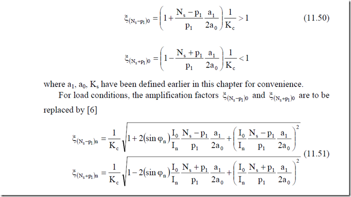
Now, for these first slot harmonics, it has been shown in Chapter 10 that their mmf companion harmonics of same order produce an increase for Ns – p1
|
and a decrease for Ns + p1, [6] |
I0 is the no-load current, In the current under load, and ϕn the power factor angle on load.
From now on using the above amplification factors, we will calculate the correction coefficients for load to multiply the various no-load stray losses and thus find the load stray losses.
Based on the fact that losses are proportional to harmonic flux densities squared, for Ns ± P1 slot harmonics we obtain
• Rotor surface losses on load
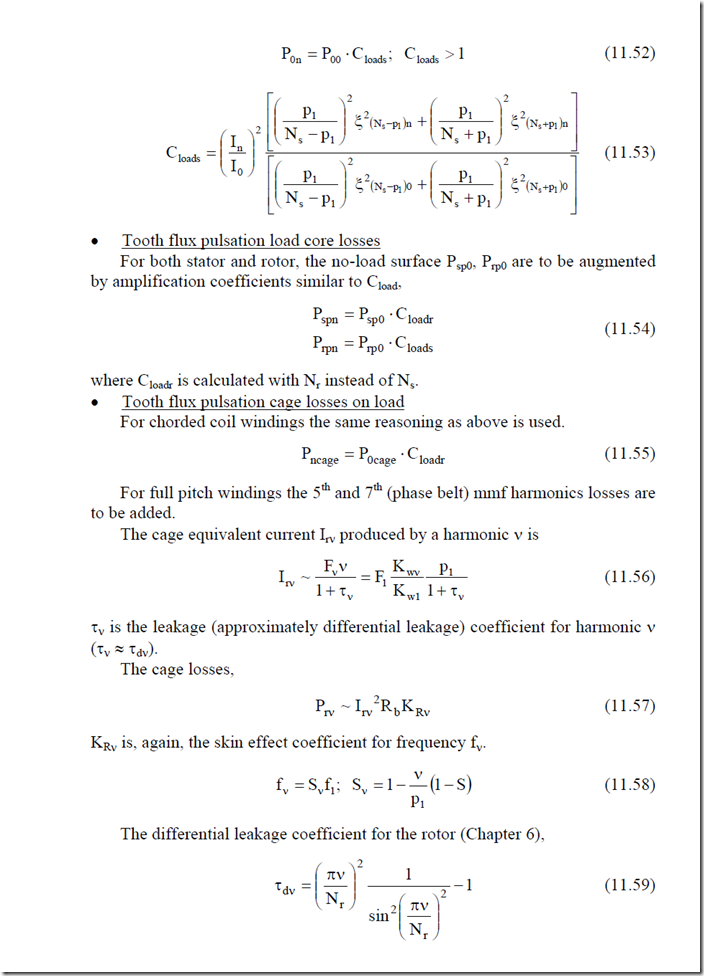
The ratio between load P0n and no-load P00 surface losses Cloads is
