Typical components
THIS CHAPTER DETAILS A CROSS-SECTION OF ELECTRICAL and mechanical components that can be found in just about any moving-carriage or EP printer. Your troubleshooting efforts will be simplified greatly if you are able to identify important components on sight, understand their purpose, and spot any obvious defects. This is by no means a complete review of every possible type of component, but it will give you a good idea of what to expect.
Mechanical components
Mechanical parts basically serve a single purpose;_!9 transfer force from one point to another. For example, a paper transport system must transfer the physical force of a paper advance motor to the paper itself to move it through the printer. This is accomplished through a series of gears, pulleys, rollers, and belts. Whenever me chanical parts are in contact with one another, they produce fric tion , which causes wear. Lubricants , bushings, and bearings work to minimize the damaging effects of friction on mechanical parts.
Gears
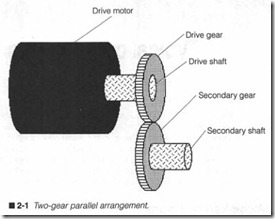
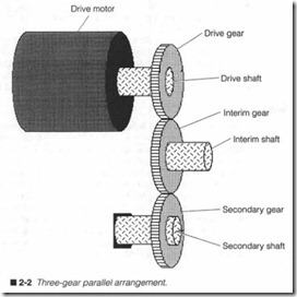
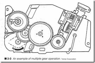
A gear performs several important tasks. Their most common ap plication is t.Q transfer mechanical force from one rotating shaft tg another. The silnplest arrangement uses two gears in tandem as shown in figure 2-1. When two gears are used, the direction of secondary rotation is opposite that of the primary shaft. If sec ondary direction must be the same, a third gear might be added as shown in figure 2-2. It is possible to change the direction of applied force by using angled gears. By varying the angles of both gears, force can be directed just about anywhere. Several secondary gears can be run from a single drive gear to distribute force to mul tiple locations simultaneously, a common tactic in complex me chanical systems like the bubble jet printer in figure 2-3.
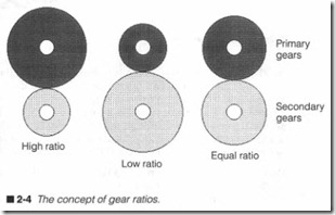
Not only can gears transfer force, they can also modify the speed and force that is applied at the secondary shaft. Figme 2-4 illus trates the effects of simple gear ratios. A gear ratio is usually ex pressed as the size ratio of the primary gear versus the secondary gear. For a high ratio, the primary gear is larger than the sec ondary gear. As a result, the secondary gear will tUTn faster, but with less force. The effect is just the opposite for a low ratio. A small primary will tmn a larger secondary slower, but with more
force. Finally, an equal ratio causes a primary and secondary gear to turn at the same speed and force.
Pulley
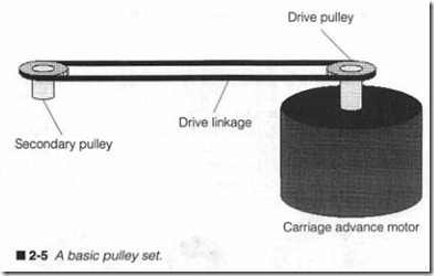
Pulley sets are used commonly in many printers. Like gears, pul leys are used to transfer force from one point to another. Instead of direct contact, however, pulleys are joined together by a drive linkage, which is usually composed of a belt, wire, or chain (much the same way as a belt in your automobile). A basic pulley set is il lustrated in figure 2-5. A motor turns a drive pulley, which is con nected to a secondary pulley through a drive linkage under tension. As the drive pulley turns, force is transferred to the secondary pul ley through the linkage, so the secondary pulley also turns. Notice that both pulleys turn in the same direction.
In addition to transferring force to a secondary shaft, the linear Oeftiright) motion of a drive linkage can be used to move a load. For example, a carriage transport system must transfer the force of a carriage advance motor to a sliding mount . If a point on the link age were connected to a carriage, the leftJright motion of the drive linkage would carry a print head back and forth. The type of pulley system used depends on the physical load that must be moved.
Pulleys and drive linkages will vary depending on their particular application. Low-force applications can use narrow pulleys (little more than a wheel with a groove in it) connected with a wire link age. Wire is not terribly rugged, and its contact surface area with both pulleys is relatively small. Therefore, wire can slide when it stretches und er tension , or if load becomes excessive. Belts and their pulleys are wider, so there is much more surface contact around each pulley. Belts are usually much stronger than wire, so ther e is less tendency to stretch under tension. This makes belt driven pulleys better suit ed for heavier loads. In practical applica tions, notched belts and notched pulleys are used in the carriage transport system. The belt is light and strong, while the notches eliminate slipping around the pulleys.
Rollers
For a printer to work at all, paper must be handled gently but frrmly. Rubber-coated rollers are ideal for this purpose; they pro vide the high friction needed to carry paper through the printer re liably and consistently, yet the pressures applied by the rollers will not damage the paper. As you might imagine, damaged, old, or dirty rollers can have an adverse effect on the paper transport system.
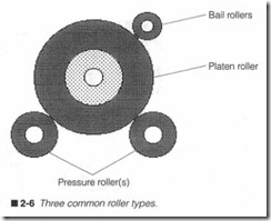
There are three types of rollers found in most moving-carriage printers: a platen, pressure (or contact) roller(s), and bail rollers. All three rollers are illustrated in figure 2-6. Your main roller is the platen. It is driven by a paper advance motor, and it provides paper support in front of the print head . The rubber also serves as a fum but pliable smface for impact printing. Pressure rollers hold paper against the platen and ensure positive traction and even pa per advance. The actual position and contact force of your pressure roller (s) will depend on the particular paper transport technique used. Bail rollers are a set of small, adjustable rollers that help to hold paper flat while it travels around the plat en on its way out of the printer.
Reducing friction
As with all mechanical systems, parts that are in contact with one another will wear while the system operates due to unavoidable friction that occurs between parts. It follows, then, that reducing friction will extend yow- printer’s working life. Lubrication, bush ings, and bearings are three commonly accepted methods of reduc ing friction.
Oils or grease have always been one answer (and might prove quite effective in small doses), but this lubrication must be replaced on a regular basis for it to remain effective. Otherwise, it can wear away, dry out, or harden into thick sludge. Lubrican ts are also notorious for collecting dust and debris from the environment, which eventu ally defeats any benefits that the lubricant can provide. When ap plying lubricants, remember to apply them sparingly.
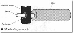
Bushings are essentially “throw-away” wear surfaces as shown in figure 2-7. A bushing is mad e of softer materials than the parts it is separating, so any friction generated by moving parts will wear out
the bushing before allowing the parts to make contact themselves.
When a bushing wears out, simply replace it with a new one. Bush ings are much less expensive and easier to replace than major mechanical parts such as slides or frames.
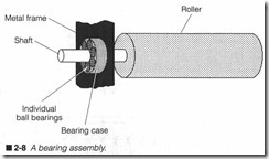
Probably the most effective devices for reducing friction between parts are bearings. Bearings consist of a hard metal case with steel balls or rollers packed inside as shown in figme 2-8. Because each steel ball contacts each load-bearing smface at only one point, friction (and wear) is substantially lower than it is for bushings.
Unfortunately, bearing assemblies are often much more expensive than bushings, so bearings are employed only to handle heavy loads, or in places that would be too difficult to change bushings.
Electromechan ical components
Electromechanical components are a particular class of devices that conver t electrical energy into mechanical force or rotation. Relays, solenoids, and motors are three common electromechani cal component s that you should und erstand and be familiar with . Each of these important devices relies on the principles of elec tromagnetism.
Electromagnetism
Whenever electrical current passes through a conductor, a mag netic field is generated around the circumference of that conduc tor as shown in figure 2-9. Such a magnetic field is capable of exerting a physical force on permeable materials (any materials that can be magnetized). The strength of a magnetic field around a conductor is proportional to the amount of current flowing through it. Higher amounts of current result in stronger magnetic fields, and vice versa.
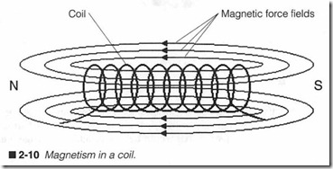
Unfortunat ely, it is virtually impossible to pass enough current through a typical wire to produce a magnetic field that is strong enough to do any useful work. The magnetic field must somehow be concentrated. This is accomplished by coiling the wire as shown in figure 2-10. When arranged in this fashion, the coil takes on magnetic poles, ju st like a permanent magnet. Notice how the direction of magn etic flux always points to the north pole. If the direction of current flow were reversed , the coil’s magnetic poles would also be reversed.
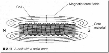
To concentrate magnetic forces even further, a permeabl e core material can be inserted into the coil’s center as in figure 2-11. TYPically, iron, steel, and cobalt are considered to be the classical core materials, but iron-ceramic composite blends (sometimes called ferrite) are used as well. It is coils of wire such as these that form the foundation of all electrom echanical devices.
Relays
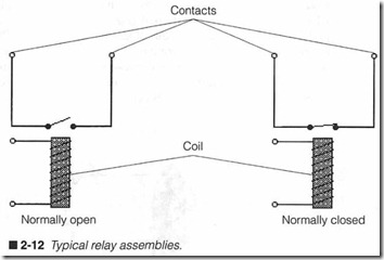
A relay is simply a mechanical switch that is actuated with the electromagnetic force generated by an energized coil. A typical re lay diagram is shown in figw-e 2-12. The switch (or contact set) might be normally open (N.O.) or normally closed (N.C.), while the coil is de-energized. When activated, the coil’s magnetic field will cause normally open contacts to close, or normally closed con tacts to open. Contacts are held in their actuated positions as long as the coil is energized. If the coil is turned off, contacts will return to their normally open or closed states. Keep in mind that a coil might drive more than one set of contacts.
Relays are not always easy to recognize on sight. Most relays used in electronic circuits are housed in small, rectangular containers of metal or plastic. Low-power relays can be fabricated into over sized IC-style packages and soldered right into a PC board ju st like any other integrated circuit. Unless the relay’s internal diagram is printed on its outer case, you will need a printer schematic or manuf actW’er’s data for the relay to determine the proper input and output functions of each relay pin.
A relay rarely fails to actuate; a simple wire coil is notoriously reli able. The problem with relays is in their contact set. Because a re lay is often used to switch relatively large amounts of cw-rent , the contacts tend to arc a bit each time the connection is made and broken. Over time, this arcing effect damages the contacts. Eventually, the contact set will become intermittent and sometimes fail to make a good electrical connection, even though the actuating coil fires just fme. To combat the arcing effect, some high-quality relays place their contact set(s) in an enclosure filled with inert gas (such as nitrogen), which will inhibit sparks. The only way to correct an intermittent or failed relay is to replace it.
Solenoids
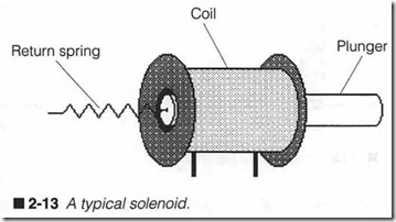
The solenoid converts electromagneti c force directly into motion as illustrated in figure 2-13. Unlike ordinary electromagnets whose cores remain fixed within a coil, a solenoid core is allowed to float back and forth without restriction . When energized, the magnetic field generated by a coil exerts a force on its core (called a plunger), which pushes it out from its rest position . If left unrestrained, a plunger would simply shoot out of its coil and fall away. Plungers are usually tethered by a spring or some other smt of mechanical return assembly. That way, a plunger will only extend to some known distance when the coil is flred, then automatically return to its rest position when the coil is off.
A common concern when using relays and solenoids is the poten tially damaging effect of “flyback voltage.” Remember that some energy is stored in the coil as a magneti c field. While current flows to energize the coil, magnetic strength remains constant. How ever, when current stops and the coil de-energizes, its magnetic field collapses very quickly. This sudden collapse induces a brief, po tentially high-voltage spike. Its polarity is reversed to that of its energizing voltage, thus the term flyback .
Such a spike would almost certainly be harmless to the coil itself (ignition coils in automobiles rely on the flyback effect to produce the high-voltage spikes that fire spark plugs), but delicate elec tronic circuits are extremely sensitive to voltage spikes. Any tran sient voltage spikes that are conducted into an electronic circuit can easily result in permanent circuit damage. A rectifier-type diode placed across a coil will work to short-out any spikes. Diodes used in this fashion are called jlyback diodes.
Solenoids have come to serve a variety of uses in printers. Ad vances in materials and assembly techniques have given rise to smaller, more efficient, and more reliable solenoids. As detailed in Chapter 3, solenoids are the key components of impact printing technology. They drive hammers or print wires that actually strike a page. Solenoids are also used in some printers with multicolor ribbons. By energizing and de-energizing a solenoid under printer control, a ribbon can be positioned at the desired color. In EP printers, solenoids are typically used as electromagnetic clutches that can engage and disengage force from the main motor to vari ous printer mechanisms. You might encounter even more exotic applications.Like the relay, a solenoid is renowned for its reliability. Chances are that the solenoid’s driving circuit will fail before the solenoid does. However, movement of the plunger within the solenoid can easily be affected by accumulations of dust and debris, as well as me chanical wear and failure. For example, the print wires of an impact dot-matrix print head can be jammed by accumulations of dried ink and paper dust. Do not presume that the solenoid is invulnerable. Often, just cleaning away accumulations of gunk can restore a jammed plunger, but a damaged solenoid must be replaced.
Motors
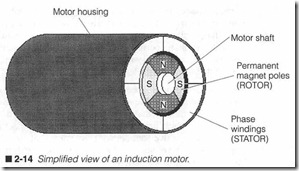
The motor is an absolutely essential part of every printer manu factured today. Motors operate the various transport systems that you will find. All motors convert electrical energy into rotating me chanical force. In turn, that force can be distributed with mechan ical parts (e.g., gears and pulleys) to turn a platen or move a carriage. An induction motor performs this task by mounting a series of powerful electromagnets (coils) around a permanent magnet core, as shown in figure 2-14. The core (known as a rotor) is little more than a shaft that is free to rotate as its poles encounter electro magnetic forces. Each coil (also called a phase or phase winding) is built into the motor’s stationary frame (or stator).
By powering each phase inits proper order, the rotor can be made to turn with a predictable amount of force. The amount of angular force generated by a motor is known as torque. Induction motors generally require two ac signals separated by a goo phase differ ence. These sinusoidal driving signals vary the strength of each phase evenly to cause a smooth rotation. Induction motors are rarely used in today’s commercial printers because they do not lend them selves easily to the precise positioning requirement s that most printers demand . Instead, a close variation of the induction motor
is used. This is called a stepping rrwtor.
Physically, a stepping motor is very similar to figure 2-14, but in stead of sinusoidal driving signals, a stepper is driven by a series of square wave pulses separated by a goo phase difference. Square waves cause the rotor to jum p (or step) in predictable angular in crements, not a smooth, continuous rotation. Once the rotor has reached its next step, it will hold its position as long as driver sig nals maintain their conditions. A typical stepping motor can achieve 1.8° per step. This means a motor must make 200 individ ual steps to complete a single rotation.
Stepping motors are ideal for precise positioning. Because the mo tor moves in known angular steps, it can be rotated to any position simply by applying the appropriate series of driver pulses. For ex ample, suppose yom motor had to rotate 180°. If each step equals 1.8°, you need only send a series of 100 pulses to turn the rotor ex actly that amount. Logic circuits in the printer generate each pulse, then driver circuits amplify those pulses into the high-power sig nals that actually operate the motor.
Motors are not quite so reliable as relays or solenoids. First, there are typically several individual coils in the motor. A weakness or failure in any one of these coils will render the motor useless. Be
cause the coils generate a relatively large amount of heat under continuous use, heat is frequently the catalyst that causes phase winding problems. The rotor is also mounted on bearings or a high-quality bushing. If the bushing or bearings wear out, the rotor will shift position and move unevenly (if at all). Damaged motors must be replaced. Fortunately, this is often a simple procedure.
Electronic components
You will fmd a wide variety of electronic components contained within your printer. Most circuits contain both active and passive components working together. Passive components include resis tors, capacitors, and inductors. They are called passive because their only purpose is to store or dissipate a circuit’s energy. Active components make up a broader group of semiconductor-based parts such as diodes, transistors, and all types of integrated circuits. They are referred to as active because each component uses a cir cuit’s energy to perform a specific set of functions; they all do something. It might be as simple as a rectifier, or as complex as a microprocessor, but active parts are the key elements in modern electronics. This section is intended to familiarize you with each general type of component, how they work, how to read their markings, and how they fail.
Resistors
All resistors ever made serve a single purpose: to dissipate power. Although resistors appear in many circuits, they are used primar ily for such things as voltage division, current limiting, volume ad justment, etc. Resistors dissipate power by presenting a resistance to the flow of current. Wasted energy is then shed as heat. Resis tance is measured in ohms using the Greek symbol Omega (Q).
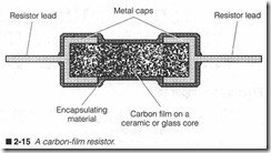
In a typical carbon-composition resistor, two component leads are insulated by a packed carbon filling. It is much harder for elec trons to pass through carbon than copper, so the flow of current is limited. The material composition of carbon filling can be altered in manufacturing to provide many different levels of resistance. Carbon-composition resistors are rarely used in modern electron ics because they are large, and they lack the precision needed to support contemporary circuits. The carbon-composition resistor has been replaced by the carbon-film type, as shown in figure 2-15. This kind of resistor uses a carbon film deposited onto a ceramic or glass core. Metal caps on both ends provide the electrical con nections. The entire assembly is encapsulated in a hard epoxy rnaterial. Carbon film resistors are far more accurate than carbon composition devices, because films are applied with more precision and control.Resistors are also rated in terms of the power that they can han dle. Common values are !-11 W, 14 W, W, 1W, and 2 W. As long as the power being dissipated by a resistor is less than its rating , the re sistor should perf orm as expected and last indefinitely. However, if a resistor is forced to exceed its power rating, it cannot shed heat fast enough to maintain a stable temperature. Ultimately, the re sistor will overheat and burn out (often damaging the printed wiring board and printed copper traces as well). In all cases, a burned out resistor forms an open circuit. A faulty resistor might appear only slightly discolored, or it might look burned and cracked. It really depends on the severity and duration of its overheating. Replace any faulty resistors wherever you might find them. If the printed wiring board is also damaged , the entire circuit assembly should be replaced to maintain peak reliability.
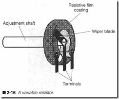
Adjustable resistors (called potentiometers or rheostats), as shown in figure 2-16, employ a movable metal wiper blade resting along a ring of resistive film. While total resistance of the film remains constant, resistance between the wiper and either end can be var ied by turning a lmob. Failures among potentiometers usually take the form of intermittent connections between the wiper blade and resistive fllm. Remember that film will wear away as the wiper moves across it. Over time, enough film might wear away at cer tain points that the wiper might not make good contact there. This can result in all types of erratic or intermittent circuit operation. Replace any intermittent potentiometers or rheostats.
Capacitors
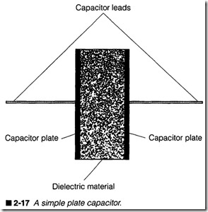
The capacitor is used to store an electrical charge. This might sound simple enough, but it has impmtant implications when com bined with other components in filters, resonant circuits, or timing circuit s. Capacitance is measured in farads (F). In reality, a farad is a very large value of capacitance . Practical capacitors are nor mally found in the microfarad (J.lF) or picofarad (pF) range. A ca pacitor is little more than two conductive plates separated by an insulator (called a dielectric), as shown in figure 2-17. The amount of capacitance is determined by plate area, the distance between each plate, and the specific dielectric material. Large val ues of capacitan ce can be achieved by rolling up a plate-die lectric assembly and housing it in a canister.
When voltage is applied across a capacitor, current flows in and electrons are stored as a static charge. As the capacitor charges, its current flow decreases. This continues until the capacitor is fully charged. At that point, no additional current flows, and the voltage across the capacitor equals the applied voltage. Keep in mind that a capacitor will remain charged even after charging volt age is removed. Large capacitors can store enough energy to pre sent a shock hazard. Ideally, charge should last indeflnitely, but internal resistance through the dielectric will eventually bleed off any accumulated charge.
There are two general capacitor types that a technician should be familiar with: fixed and electrolytic. Fixed capacitors are nonpo larized devices; they can be inserted into a circuit in any orienta tion. Many fixed capacitors are assembled as small wafers or disks. Conductive plates are typically aluminum foil. Common dielectrics include paper, mica, and ceramic. The assembly is then coated with a hard plastic, epoxy, or ceramic housing to keep out humidity. Larger devices can be assembled in cans that are sealed hermeti cally. Electrolytic capacitors are polarized components; they must be inserted in the proper orientation with respect to applied volt age. An aluminum electrolytic capacitor is made using two strips of aluminum alloy (one strip is coated to prevent oxidization) sep arated by a layer of gauze soaked with an electrolyte paste of boric acid, glycerin, and ammonia. The assembly is rolled up tightly and sealed into a metal canister. Each plate is welded to leads that con nect the component. Tantalum electrolytic capacitors are con structed differently. An anode of sintered, porous tantalum powder is housed in a silver-plated container with an electrolyte of sulfuric acid or some other electrolyte. The small devices are then dipped in ceramic or epoxy.
Like resistors, capacitors tend to be rugged and reliable devices. Because they only store energy (not dissipate it), it is virtually im possible to burn them out. Remember that capacitors do have some internal resistance. Ideally, this would be infinite, but it is actually somewhat less. Under heavy loads, a capacitor’s internal resis tance can dissipate power and cause heating over time. Capacitors are subject to dielectric breakdown due to electrical causes (like severe voltage overloads) or environmental causes (such as plate corrosion due to humidity penetration). These failures generally manifest themselves as open or short-circuit conditions within a capacitor. Most breakdowns are invisible from the part’s exterior, but are measurable with test instruments.
Electrolytic capacitors are not only subject to dielectric break down and evaporation, but they can also explode if enough energy is applied in the reverse polarity. A failure elsewhere in the circuit (or your incorrect placement) can reverse the voltage across a ca pacitor. This causes temperature and pressure to rise inside until its enclosure ruptures. The explosion is rather like a frrecracker, a bang with smoke and shards of foil and electrolyte. Take care that aluminum shards do not settle back onto the circuit and short out any other components. Electrolytic capacitors also fail from “fa tigue” due to frequency stress. For example, it is not uncommon to find filter capacitors that have failed in switching power supplies. Reversed tantalum capacitors can also rupture or shatter, but most often its outer casing will crack. Heat and pressure might force out some internal material. Make sure that there is no tanta lum “spatter” bridging across other components.
Inductors
An inductor is used to store a magnetic charge for much the same reasons that a capacitor is used to store an electrical charge. Ad vances in solid-state electronics have rendered inductors essen tially obsolete for traditional applications such as resonant circuits and filters, but they remain invaluable for such high-energy com ponents as transformers, motors, and solenoids. All inductors are measured in henries (H), although some small inductors are mea sured in millihenries (mH) or microhenries Q.LH).
A transformer is actually a combination of inductors working to gether. It is composed of several important parts (as shown in figure 2-18), a primary winding, a secondary winding, and a core struc ture. An ac voltage is applied across the primary winding. The ac voltage is constantly changing its value and reversing its polarity over time. As a result, the magnetic field generated in a primary coil also fluctuates. When the fluctuating magnetic field intersects a secondary winding, an ac voltage is created (or induced) across it. This principle is known as magnetic coupling. Notice that the primary and secondary coils are wound around the same core. A common core concentrates magnetic energy and provides effi cient coupling to the secondary coil. Although figure 2-18 shows only one secondary coil, there might be several secondary coils in a transformer.
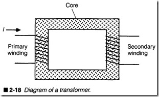 The actual voltage generated in a secondary coil depends on the ratio of primary windings to secondary windings. This is known as the turns ratio. If your secondary coil contains more turns than the primary coil, then ac induced on the secondary will be greater than primary voltage by a factor of the turns ratio. For example, if a transformer has 250 turns in its primary and 500 turns in its sec ondary, its turns ratio is 1:2 (0.5 tr). This means that 10 Vac ap plied to the primary will yield [10/0.5 tr] 20 Vac. Such an arrangement is known as a step-up transformer. If the situation were reversed with 500 turns in the primary and 250 turns in its secondary, your transformer’s turns ratio would be 2:1 (2 tr). If 30 Vac were applied to the primary, its secondary voltage would be [30/2 tr] 15Vac. This is called a step-down transformer.
Current is also stepped in a transformer, but opposite to the direc tion of voltage steps. Ifvoltage is stepped down, current is stepped up by the same ratio, and vice versa. For the step-up transformer above, if your 10-Vac input carries a current of 1A, the 20-Vac out put would only supply a current of [1 x 0.5 tr] 0.5 A. With a step down transformer, an input of 30 Vac at 1 A would supply an output of 15 Vac at [1 x 2 tr] 2 A. Ideally, output power should equal input power. For example, an input of 30 Vac at 1A is [30 V x 1A] 30 W, and the output of 15Vac at 2 A is [15 V x 2 A]30 W. In reality, output power will always be slightly less than input power due to losses in the windings and core; no device is 100% efficient at transforming power.
Because inductors are energy storage devices, they should not dis sipate any power themselves. However, the resistance of wire in each coil, combined with magnetic losses through the core, does al low some power to be lost as heat. Heat buildup is the leading cause of inductor failure. Wrre used in transformer windings is solid and insulated with a thin, tough coating of enamel. Long-term expo sure to heat can break down enamel and begin to short-circuit the windings. This lowers a coil’s overall resistance and draws more current, creating even more heat. Breakdown accelerates until the coil is completely shorted, or until heat burns a winding apart to open the circuit. You cannot see a failing transformer, but be sus picious of any transformer or coil that seems unusually hot, espe cially if the circuit has not been on for very long. You can also detect a developing heat failure by a strong, pungent odor of burn ing enamel.
Diodes
Diodes are two-terminal semiconductor devices that allow current to flow in one direction only, but not in the other. This property is known as rectification. As detailed in Chapter 8, rectification is essential to the operation of every power supply.
Because diodes only operate in one direction, they are polarized devices as shown in figure 2-19. General-purpose rectifier-type diodes are available in a variety of case styles depending on the amount of current that must be carried. Glass-cased diodes are of ten used for low-power (or “small-signal”) applications. Plastic or ceramic-cased diodes are moderate power devices, generally used for power supplies, circuit isolation, and inductive flyback protec tion. Metal-cased, stud-mounted devices are for high-power recti fication. The schematic symbol representing rectifier-type diodes is also shown in figure 2-19.
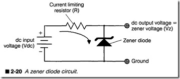
You should be concerned with two key diode specifications: for ward current (IF) and peak inverse voltage (PIV). When a diode is forward-biased, it develops a constant voltage drop of about 0.6 V (for silicon diodes) and current begins to flow. This is called for ward current, and it is limited by resistance in the circuit. If ex cessive current flows, the diode will be destroyed by heat. Diodes that are biased in the reverse direction are off. A reversed diode acts like an open switch, so it will not conduct current. Applied voltage appears across the diode. Even if this reversed voltage were increased, the diode will not conduct, up to a point. If the re versed voltage exceeds your diode’s PIV, its semiconductor junc tion can rupture and fail as either an open or short-circuit.Zener diodes are a unique species designed to operate in a reverse voltage environment, as illustrated in figure 2-20. Notice the new schematic symbol for a zener diode. When applied voltage is below the zener diode’s “breakdown voltage” (usually 5, 6, 12, or 15 V), voltage across the zener equals the applied voltage and no zener current will flow. As applied voltage exceeds the zener’s breakdown rating, current will begin to flow and zener voltage remains clamped at its rated breakdown voltage. Excess voltage is then dropped across the current-limiting resistor. This makes zener diodes per fect for use as simple voltage regulators or signal level clamps.
Electrons must bridge a semiconductor junction in order to oper ate. If the junction is constructed with special materials and en capsulated inside a diffuse plastic covering, electrons moving across the junction will liberate photons of light. This is the basic principle behind light emitting diodes (LEDs). A typical LED cir cuit is shown in figure 2-21. Like rectifier-type diodes, LEDs can only be powered in one direction, but their forward voltage drops are higher (0.8 to 2.8 Vis common), and they require 20 to 30 rnA of current for proper lighting.
Sudden or severe overloads can cause a diode to crack or shatter; these are usually easy to spot with some careful observation. Un der most circumstances, however, they show no outward signs of failure, so you will require test instruments and patience to isolate a defective diode. Diodes generally fail as open or short-circuits.
Sudden or severe overloads can cause a diode to crack or shatter; these are usually easy to spot with some careful observation. Un der most circumstances, however, they show no outward signs of failure, so you will require test instruments and patience to isolate a defective diode. Diodes generally fail as open or short-circuits.
Transistors
Transistors are three-terminal semiconductor devices whose out put signal is directly controlled by its input signal. This kind of op eration makes transistors particularly well suited for signal amplification and switching tasks. Two major families of transis tors have been developed, as shown in the schematic diagrams of figures 2-22 and 2-23. Bipolar transistors are common, inexpen sive, general-purpose amplifiers and switches. You will probably encounter bipolar transistors in most conunercial printer circuits. Field effect transistors (FETs) and metal oxide semiconductor FETs (MOSFETs) are also used, but not as often. Unfortunately, there is just not enough room in this book to discuss the charac teristics and operation of each transistor family, but it is important that you realize they are all transistors, and that you can identify them on sight should they ever appear on a schematic.
TransistorsTransistors are three-terminal semiconductor devices whose out put signal is directly controlled by its input signal. This kind of op eration makes transistors particularly well suited for signal amplification and switching tasks. Two major families of transis tors have been developed, as shown in the schematic diagrams of figures 2-22 and 2-23. Bipolar transistors are common, inexpen sive, general-purpose amplifiers and switches. You will probably encounter bipolar transistors in most conunercial printer circuits. Field effect transistors (FETs) and metal oxide semiconductor FETs (MOSFETs) are also used, but not as often. Unfortunately, there is just not enough room in this book to discuss the charac teristics and operation of each transistor family, but it is important that you 

realize they are all transistors, and that you can identify them on sight should they ever appear on a schematic.
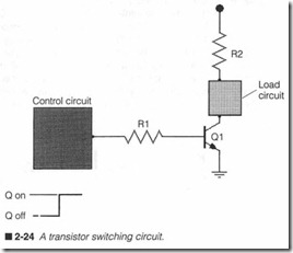
Because computer printers are almost exclusively digital devices, discrete transistors are primarily used in switching circuits, such as the one shown in figure 2-24. Unlike an amplifier whose output varies in proportion to its input, a switch is either totally on or to tally off. Digital signals from simple logic gates are often used as control signals to operate a transistor switch. A logic “0” (0 V) in put leaves the transistor off, while a logic “1” (5 V) input turns the transistor on.A resistor is added to the base lead for current limit ing purposes. When a transistor is on, cunent flows through the load, into the collector lead, then through the emitter lead to ground. Additional current limiting might be needed to restrict current flow in the collector. You will see switching circuits used in a wide range of driver applications.
There are many electrical specifications that describe particular transistors, but there are four that you should understand when looking for replacement parts. Base current (IJ refers to the maximum current that can flow into a base lead. Ib is usually under 1rnA Collector current (Ic) specifies the lirnlt of current that can flow through the collector. Small-signal transistors might allow up to 100 rnA through the collector, while high-power transistors might allow collector currents as high as 10A or more. Gain (beta, hfe, or p) indicates how much base current will be amplified in the transis
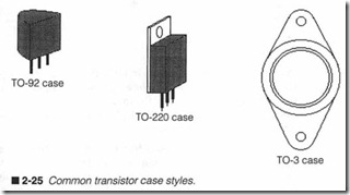
tor. Finally, collector-emitter voltage ( describes a voltage drop from collector to emitter when the transistor is turned on fully.Transistors from any family are available in several case styles de pending on the amount of power they can dissipate. Figure 2-25 shows several typical case styles. Low-power devices are often pack aged in T092 cases. Medium-power transistors use larger T0220 cases with a metal mounting frame. A heat sink can be attached to help dissipate excess power. The T03 case is an all metal casing used for high-power transistors. Two moilllting holes allow the case to be attached to a metal heat sink or chassis for best power dissipa tion. As you can see, the size of a case is relative to the amount of power that a transistor dissipates. The rapid trend toward smaller circuitry has also introduced surface mount transistors.
As with diodes, transistors rarely show any outward signs of fail ure, but excess heat or electrical stress can cause semiconductor jllll ctions to become open or short-cir cuited. You must determine the failed transistor by measuring its operation with test equip ment in a running circuit, or remove the questionable device and measure its static operation with a transistor check er.
Optoisolators
Optical isolators, also known as optoisolators, are used as position and proximity sensors within the printer. They can also be used to electrically isolate signals between circuits. A basic optoisolator is shown in figure 2-26. The signal to be isolated (usually digital) is fed to the “transmitter” portion of the device. Transmitters can use vis ible light or infrared (IR) LEDs. Light travels across a physical gap to the “receiver.” Instead of current flowing into a transistor’s base lead, a phototransistor’s base generates current when stimulated by light. Notice the schematic symbol for a standard phototransistor. ‘Vhen the LED turns on, its light activates the phototransistor, which reproduces the original signal in its output circuit.
The advantage of this type of circuit is that input and output cir cuits are completely isolated. Note that there is absolutely no elec trical connection between both circuits, only a light signal. This is ideal for isolating low-power digital circuits from high-power driver circuits, or vice versa.
Suppose a slot was provided between the transmitter and receiver of figure 2-26 to form a position sensor. The transmitter is usually turned on at all times. It is the presence or absence of an object in the slot that turns the receiver on or off. Suppose the slot in figure 2-26 was clear (unobstructed). Transmitted light would simply cross to the receiver and turn it on. With the output circuit shown, an excited transistor pulls its output low. If an opaque object should enter the slot, light will be interrupted and the receiver will tum off. Signal voltage will rise to indicate that something has been detected. This type of sensor is commonly used in printers to sense the presence of paper, or the home position of a print head.
Optoisolators are also key components in optical encoders. Mov ing-carriage printers must keep track of the print head’s position at all times. Optical encoders provide feedback to the print er control circuits that confirm the carriage is in fact where it is intended to be. As a carriage moves, the encoder generates digital pulses that are interpreted as distance and direction by main logic circuits.
Optoisolator s do not carry significant amounts of curr ent, so breakdowns due to electrical overloads or heat are virtually im possible. What you should be concerned with is any accumulation of dust or debris that might interfere with the transfer of light from transmitter to receiver. Severe interference can easily cause sen sor errors. Electrical problems must be isolated with test equip ment while the printer is in operation.
Integrated circuitsIntegrated circuits (ICs) are the most powerful and diverse group of electronic components that you will ever deal with. They are the “building blocks” of modem electronics that can take the form of amplifiers, memories, microprocessors, digital logic, oscillators, regulators, or a myriad of other analog or digital IC functions. It is impossible to determine the specific function of an rc ju st by look ing at it. You must refer to the printer’s schematic (or manufac turer’s data for the particular part) to determine the function of each IC pin .
