If you were to find yourself in a foreign land and unable to read or speak the language, you would see the familiar things such as buildings , automobiles, newspapers, and people, but you would not be able to understand what was going on around you If you could speak and understand the oral language but ·
could not read the printed words, you still would be dependent upon someone else for a full understanding. The same thing applies to control work. If you have mastered the first four chap ters of this book , you can now speak and understand the oral language of controls. Until you master the control diagrams, however, you will be dependent upon someone else for most of your information.
This chapter deals with the written language of control and control circuits . Do not be satisfied until you can read and under stand control prints readily and with reasonable speed. When you learned to read English, you first learned the 26 letters of the alphabet that are arranged into combinations to form all the words we use. The same thing is true in the language of control. There are only a few basic symbols that are used to express the meaning and purpose of the control circuit. The chief difficulty is that while there is a standard for symbols,1 there is no real standard usage and sometimes it is necessary to do a little guessing as to what a symbol means.
The symbols used in this chapter are those in most common use.
5 ·1 SYMBOLS
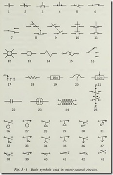
With reference to Fig. 5 ·1, symbol 1 represents a normally open contact that is automatically operated. It might represent a line contact on a starter, the contact of a limit switch, the contact of a relay, or any other control device that does not require manual operation. Symbol 2 represents a normally closed auto matic contact, and all that applies to symbol 1 applies to symbol 2 also, except its normal position. The method of telling what operates this type of contact will be discussed under Sec. 5 ·2.
Symbol 3 represents a manually operated , normally open con tact of the push-button type. Symbol 4 represents the same type of contact except that it is normally closed. Symbol 3 for the normally open push button should be drawn so that there is space between the dots and the cross bar, but it is not always drawn with such care. If the cross bar is above the dots, the symbol is for a normally open contact, even though the bar may be touching the dots. Symbol 4 should be drawn so that the cross bar just touches the bottom of the dots, but again this is not always done. If the cross bar is below the dots, then it is normally closed even though the bar does not touch the dots. A good way to remember this is to picture the symbol as being a drawing of a push button, which it is. If you push on the button part, represented by the vertical line, the cross 1 NEMA ICS-1970, part ICS 1-101.
bar will move downward . When it is above the dots or contact points, the pressure will close them. When it is below the dots, it will move them apart and open the circuit.
Symbols 5 and 6 represent manual contacts of the toggle switch type, 5 being normally open and 6 being normally closed .
Symbol 7 is a toggle switch of the single-pole double-throw ( SPDT) type, where one contact is normally open and the other normally closed.
When more tha n one set of contacts are operated by moving one handle or push button , they are generally connected by dotted lines, as in symbols 8 and 9. The dotted iines represent any form of mechanical linkage that will make the two contacts operate together. One other method that is used frequently to show push buttons that have two sets of contacts is shown in symbols 10 and 11. Symbol 10 has two normally open contacts, and symbol 11 has one normally open and one normally closed contact.
Symbol 12 is a pilot light which is identified chiefly by the short lines radiating out from the center circle.
Symbol 13 represents a coil. It might be a relay coil or a solenoid coil or the closing coil on a starter. Later we shall discuss how to tell which it is. Symbol 14 also is used to repre sent an operating coil.
Symbol 15 represents the heating element of an overload relay.
Symbol 16 is a rotary selector switch. The same type of switch is shown by symbol 17.
Symbols 18 and 19 show two ways that resistors are drawn . Symbols 20 and 21 are variable resistors. Capacitors are shown in symbols 22 and 23. Symbol 24 is used to represent a trans former. Symbol 25 shows a plugging switch, which stops plugging action after drive has practically come to rest.
There is a need in some diagrams for clarifi cation of specific devices and their operation; the additional symbols 26 to 43 are NEMA approved. Symbols 26 and 27 represent normally open and normally closed liquid-level switches. Symbols 28 and 29 represent normally open and norm ally closed vacuum or pressure switches. Symbols 30 and 31 represent tempera ture activated switches. Symbols 32 and 33 represent flow switches.
Symbols 34 and 35 represent timer contacts which have delay on energizing (TDOE). Symbols 36 and 37 represent timer contacts which have delay on deenergizing (TDODE).
Symbols 38 and 39 represent direct-actuated limit switches. Symbol 40 represents a normally open limit switch which is held closed. Symbol 41 represents a normally closed limit switch which is held open.
Symbols 42 and 43 represent foot switches.
With English or any other language, the meaning of a word depends to some degree upon how it is used, and so it is with the language of control symbols. As we progress through the study of control circuits, we shall develop these few basic sym bols into words and sentences that will tell the story of what functions are to be performed by the control components repre sented in the diagram by symbols.
5.2 DIAGRAMS
The control diagram is the written language of control circuits, and it takes several different forms to fit the particular needs for which it is to be used. As with all languages, the same form will not suit all needs. Some things are better expressed by poetry, while others are best written in prose. There are three general types of control diagrams in use.
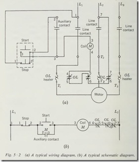
The first of these is the wiring diagram (Fig. 5 ·2a) , which is best suited for making the initial connections when a control system is first wired or for tracing the actual wiring when troubleshooting.
The second type is a schematic or line diagram (Fig. 5·2b), which is by far the easiest to use in trying to understand the circuit electrically. Most circuit diagrams are first developed by drawing a schematic diagram.
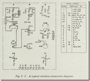
The third type is the wireless-connection diagram (Fig. 5 ·3) , which has very few claims to usefulness except that it is compact and saves confusing lines when many wires must be shown. Its chief advantage is for installing already-formed wiring harnesses for factory assembly lines.
5 ·3 WIRING DIAGRAMS
Wiring diagrams (Fig. 5 ·2a) are developed by drawing the sym bol for each component in its proper physical relationship to the other components and then drawing the wires between the proper terminals. In other words, it is a drawing of the equip ment and wires more or less as they will be run on the job . Therefore, we can say that the wiring diagram is a representation
of the control circuit in its proper physical relationship and se quence. Its chief advantage is that it helps to identify compo nents and wires as they are found on the equipment. Symbols as used in the wiring diagram (Fig. 5 ·2a) are usually a pictorial representation of the components with the contacts and coils in their proper physical relationship.
5 ·4 SCHEMATIC DIAGRAMS
The schematic diagram (Fig. 5 ·2b) is a representation of the circuit in its proper electrical sequence. Assume that you have wired a part of a control circuit beginning at line 1 and con tinuing through each contact, switch, and coil until you reached line 2. If all the contacts, switches, and coils are free of their mountings and the wire is out in the open, you can take each end of the wire and stretch it tight. What you would see would be a straight wire, broken in places by the contacts, switches, and coils. This is what you see in a schematic diagram. Each line from line 1 to line 2 represents a wire and its associated components as it would appear if stretched out in the above manner. A careful study of the diagrams in this chapter will show you that the more complex circuits have several of these wires or lines stretched out and that each of them is a small circuit within itself.
The chief advantage of the schematic diagram lies in the fact that it shows the circuit in its proper electrical sequence. Each component is shown where it falls in the electric circuit without regard to its physical location. There is no diagram that can compare with the schematic diagram for obtaining an under standing of a control circuit or for locating trouble in a control circuit.
To read a schematic diagram, start at the left-hand side of the top line and proceed to the right. If a contact is open, the current will not go through; if it is closed, the current will go through. In order to energize the coil or other device in the circuit, you need every contact and switch closed to form a complete path. In other words, if there is an open contact, the coil will be dead; if not, it will be energized. Remember that con tacts and switches are shown in their normal, or deenergized, position.
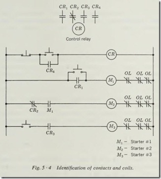
The symbols used in schematic diagrams must have some means of telling you what operates them and on what compo nent they will be found. Since we have put them in their electri cal instead of their physical position in the circuit, the several contacts of a relay might be scattered from one end of the dia gram to the other. In order to identify the relay coil and its several contacts, we put a letter or letters in the circle that repre sents the coil (Fig. 5 ·4). Each of the contacts that are operated by this coil will have the coil letter or letters written next to the symbol for the contact. Sometimes, when there are several contacts operated by one coil, a number is added to the letter to indicate the contact number, generally counted from left to right across the relay.
While there is a standard 1 for the meaning of these letters, most diagrams will have a key or list to show what the letters mean, and generally they are taken from the name of the device. For instance, the letters CR generally are used to indicate the coil of the control relay. The letters FS are used frequently to show a float switch. The letters LS are used to show a limit
1NEMA ICS-1970, part ICS 1-101.
switch. Quite frequently, when several motor starter coils are shown on one control diagram, such as a circuit for sequence operation of several motors, the starter coil may be shown with the letters M1, M2, M3, etc., for the total number of motors.
5 ·5 DEVELOPING A SCHEMATIC DIAGRAM
In order to see the relationship between the schematic and the wiring diagrams, suppose we develop a schematic diagram from a wiring diagram (Fig. 5 ·2). This method of development is highly recommended for use in the field when a schematic is needed but not available. The first step is to number the wires of the control circuit. Start where the control wire leaves L1, and number each end of each wire. Change numbers each time you start another wire until you reach L2, or the end of the control circuit. In Fig. 5 ·2a we numbered the wire from L 1 to STOP button 1 and placed the numeral 1 at each end. The wire going from the other side of the STOP button to the START button and to terminal 2 of the starter auxiliary contact is num bered at each of its three ends with the numeral 2. The wire that connects the other side of the START button to terminal 3 of the starter auxiliary contact and the starter coil is numbered
3. A wire from the starter coil to the first overload contact is numbered 4. The wire between the two overload contacts is numbered 5. The wire from the second overload contact to L2 is numbered 6.
To draw the schematic of this circuit, the first step is to draw two vertical lines, one on each side of the paper (Fig. 5 ·2b). Now draw a short horizontal line to the right from L1 and number each end with numeral 1. This represents wire 1 of the wiring diagram, which ends at the STOP button. Draw the symbol for the STOP button at the end of this line. Now draw wire 2 from the STOP to the START button and down to the auxiliary contact. Note that this is shown as an automatic contact operated by coil M; therefore it is labeled M to show what oper ates it. Continue the circuit horizontally across the paper, follow ing the numbers on the wiring diagram, until you reach L2. Be sure to show each contact in its normal, or deenergized, position. When a wmng diagram is needed and only a schematic
is available, the reverse of the above method should be used.
To read the schematic diagram in Fig. 5 ·2b, start at L 1, which is a hot line, and follow the circuit across the page. First we come to the STOP button. It is normally closed so that the current can flow through, and we can proceed to the START button and auxiliary contact M. Both of these are normally open, so the current cannot go any farther. Contact M closes when coil M is energized, so we cannot complete the circuit that way. The START button can be pushed, which will close its contacts and allow current to flow to the coil M and on through the two normally closed overload contacts, marked OL, to L2. This completes the circuit to coil M, and it closes the starter and contact M. When we release the START button, thus opening its contacts, the coil does not drop out, because contact M is now held closed by coil M. The motor is now running and will remain so until the control circuit from L 1 to L2 is broken.
To stop the motor manually, all that is needed is to push the STOP button, which interrupts the circuit at this point, caus ing an interruption of current to coil M and dropping out the contacts of the starter. Contact M being operated by coil M is now open, so that when we release the STOP button, the coil is not energized again. Note that when the motor draws too much current, one or both overload contacts will be opened, thus interrupting the circuit between coil M and L2. The result of opening the circuit at this point is the same as that of pushing the STOP button.
While this is a simple circuit and fairly easy to follow on either diagram, the same system for the development of the sche matic diagram and analyzing the control circuit will work re gardless of the complexity of the circuit.
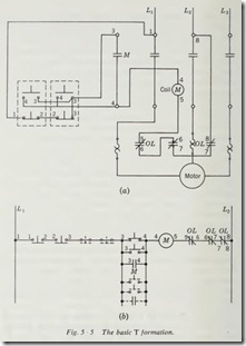
Suppose now that we add one more START-STOP station to the circuit in Fig. 5 ·2a. The new circuit is shown in Fig. 5 ·Sa. If you look at the numbering of the wires in the wiring diagram, you will see that it goes from one to seven. This increase in total numbers is caused by the insertion of the extra STOP button in the circuit. If we follow the same technique used on Fig. 5 ·2b, we shall develop the schematic diagram of Fig. 5 ·5b, which starts at Ll and proceeds horizontally through the first STOP button, the second STOP button, and the first START button, which is paralleled by the second START button and auxiliary contact. From there it proceeds to the coil of the starter marked M and thence to the first overload contact and the second over load contact to £2.
As in the preceding circuit, the STOP buttons will be closed in their normal position so that current can flow from L 1 as far as the parallel group of START buttons and the auxiliary con tact. Current can flow from L2 through the normally closed overload contacts to the coil M, so that now all that is needed to start the motor is to close one of the START buttons. Since the START buttons are in parallel, either of them will complete the circuit from L 1 to coil M, so that it makes no difference which one is pushed in order to energize the coil.
It should be noted that there are two additional STOP buttons ,
two additional START buttons, and an additional contact shown dotted on this diagram. They indicate additional controls as they would be added to this circuit. Careful note should be taken of this diagram, since it is the basic T formation which is as sumed by any circuit with multiple control components used to control a single coil. You will note that all the STOP buttons are connected in series from one side of the line or the other. The start components, in this case consisting of two or more START buttons and one or more contacts , are in parallel. The value of this T formation lies in understanding that if any control component, regardless of its type, is to be used to stop the motor , it will be placed in series with the STOP button ; if it is to be used to start the motor, it will be placed in parallel with the START button. In short, if you can draw, read, and understand the circuit of Fig. 5 ·2b, then you can develop more complex circuits by the addition of components to perform the function of stop in series with the original STOP button and to perform the function of start in parallel with the original START button.
5 · 6 ADDING CIRCUIT ELEMENTS
Suppose that you are instructed to add a limit switch, float switch, or push button to an existing circuit. Then , if this compo nent is to be used to stop the motor, all that is necessary is that you locate the wire connecting Ll to the STOP button or other components and break it at some point through the new control component.
Suppose instead that you are required to install a control com ponent such as a limit switch, float switch, or push button to perform the function of start for the motor. Then all that is required is that you parallel the new component with the existing start component. These additional components are represented in Fig. 5 ·5b by those components shown dotted.
It should be noted also that components used to perform the function of stop are normally closed components. That is to say, their contacts are in the closed position whenever the com ponent is deactivated. Those components which are to perform the function of start are normally open components. In other words, their contacts are open in their deactivated state. There is no limit to the number of components that can be added in series with the STOP button of the simple circuit shown in Fig. 5 ·2b to perform the function of stop, nor is there any limit to the number of components that can be added in parallel with the START button to perform the function of the start for the coil M.
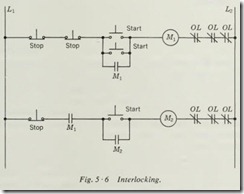
Consider the circuits shown in Fig. 5 ·6. The top circuit is the same as that shown in Fig. 5 ·5b. The current can flow through both of the normally closed STOP buttons as far as the START buttons. All that is required to energize the coil is to push the START button, thus closing its contacts and energizing coil Ml. Coil Ml, in turn, closes contact Ml in parallel with the START buttons, thus maintaining the circuit to coil Ml.
Now look at the bottom circuit, and you will see that the current can flow from Ll through the normally closed contact only as far as the normally open contact Ml. This contact must be closed in order to energize coil M2 through the START button. This contact has an identification M 1, which indicates that it would be closed whenever coil Ml is energized. This means, then, that the motor which is energized by coil Ml must be running before we can start the motor which is energized by coil M2. If we start motor Ml by pushing the START button, coil Ml is energized, thus closing both contacts labeled MI. The contact in parallel with the START buttons is used to main tain the circuit to coil MI. The contact in the lower circuit, labeled M 1, will be closed and will allow current to flow as far as the START button . When this START button is pushed, current can reach coil M2. Energizing this coil closes contact M2, maintaining the coil circuit and permitting the second motor to run.
Consider what happens if we push the STOP button of coil Ml. This will break the circuit and deenergize coil Ml, thus dropping out all its contacts. This will open the maintaining contact in parallel with its START buttons and the contact in series with the STOP button of coil M2. Opening of the contact in series with this STOP button will deenergize coil M2, which will drop out its contact M2, and both motors will be stopped, even though the button we pushed was in the circuit for motor MI. Circuits of this type are frequently used for multiple con veyor-belt operation, where the first conveyor must not run unless the following conveyor is running, thus preventing material from piling up where the two conveyors converge.
Actually we have considered only three fairly simple basic control circuits. These circuits, however, represent the majority of conditions that are found in the most complex control circuits. The same type of analysis of the operation of the electric circuit will enable you to understand many circuits which now might puzzle you considerably. In Chap. 7 we shall consider many more complicated circuits and develop a system for analyzing their operation.
Summary
In this section we have discussed in some detail the schematic diagram. The emphasis has been put on the schematic diagram because it is the type of diagram which transmits to the reader the most concise and understandable electrical information about the control circuit. The same procedure for reading and understanding the control functions of a circuit from the sche matic diagram also applies to the wiring diagram. When it is necessary to use a wiring diagram to analyze or understand the control circuit, it is necessary that you trace each wire, beginning at the source of power and noting each component or contact that is in the circuit and what its function might be. It is highly recommended that on the more complicated circuits, if a sche matic diagram is not available, you develop such a diagram using the methods put forth in this chapter. Understanding the circuit will be much easier when this procedure is followed.
To read a wireless-connection diagram, the same principles apply except that you must find the proper component by com paring the number of the wire indicated as it leaves a terminal of each piece of equipment. Caution is needed to be sure that you have found all of the places where a particular wire is con nected by finding all the points labeled with the same numeral. Again it is suggested that you develop a schematic diagram from the wireless-connection diagram before attempting analysis of the control circuit if it contains more than a very few components.
Should it be desired to have a wiring diagram when only a schematic diagram is available, one can be developed by apply ing the reverse of the procedure outlined for the development of a schematic diagram from a wiring diagram. Draw each com ponent to be used in the circuit in its proper physical relation ship. Now number each wire on the schematic diagram as we have been doing. Then number each terminal of each component on the wiring diagram as it is numbered on the schematic. All that is left is to connect corresponding numbers by wires or lines on the drawing, and you will have a wiring diagram which represents the electric circuit shown on the schematic diagram.
In order to understand the symbols as found on drawings or diagrams made by various pE )pie, you should study manufac turers’ booklets and control-circuit diagrams that can be obtained from the manufacturers of control equipment. This study will enable you to become familiar with the many types of symbols used to represent a single component just as your understanding of the spoken or written word in English depends upon the size of your vocabulary. The knowledge of words and phrases in English makes it easier for us to understand the spoken and written word as it is presented by various people, and so it is with control circuits. The greater your knowledge of the symbols in use and the components that will be used to perform the functions of control, the better will be your under standing of the various diagrams and circuits as drawn by the · many people engaged in this work.
Review Questions
1. Draw a symbol for a START push button.
2. What method is used to show two contacts which are me chanically connected so that they operate simultaneously?
3. When a push button is intended to be normally closed, is the cross bar drawn above or below the contact dots?
2. What is the chief advantage of a wmng diagram?
3. What is the chief advantage of a schematic diagram?
4. What is the chief advantage of a wireless-connection diagram?
5. Components which are to be used to perform the function of stop are connected in .with each other.
6. Components which are to perform the function of start are connected in with each other.
7. How are contacts identified to show what operates them?
8. How is a schematic diagram developed from a wiring diagram?
11. How is a wiring diagram developed from a schematic diagram?
