When the welder is up to speed and ready to weld, the conductors of the armature are cutting the lines of force of the shunt field, creating full voltage. At this time, voltage between the welding rod and the metal to be welded is at its highest value.
When the welding rod strikes the metal, there is a short circuit and the ampere demand is very high. High amperes flow through the series field and create a canceling flux. The canceling flux lowers the voltage output of the generator, reducing the chance of the rod fusing to the iron. The reaction of the series field, however, isn’t quick enough to prevent the fusing. (This is why a reactor is needed.)
Operation of the Welder’s Reactor
Sudden high amperes are delayed (and lowered) as they go through the reactor. The delay is caused by the magnetizing of the reactor’s iron.
This electrical delay allows the operator to start the welding arc without the rod fusing to the iron.
An arc has much higher resistance to current flow than when the rod is shorted to the metal. The higher resistance of the arc will cause a sudden drop in ampere flow. At this time, the reactor iron is highly magnetized. When the amperes drop suddenly, the magnetic field of the reactor collapses. As the magnetic field collapses, its lines of force cut the conductors of the reactor, creating a voltage. This voltage adds to the generator’s voltage, maintaining the arc. Without the reactor, the arc would extinguish.
Without the reactor’s effect, the rod would tend to stick or fuse to the metal. An arc would be hard to establish and maintain. The series field
alone wouldn’t react fast enough. The reactor is a very important part of the DC welder’s operation.
Interpoles
The purpose of interpoles is to reduce brush arcing. An interpole is a coil of heavy wire around an iron pole piece. Interpoles are usually connected in series with each other. As a unit, they’re connected between Al and the armature or between the armature and A2. Their leads are usually connected internally to the brush holder (with no external accessible leads). Interpoles can be reversed internally to suit the application.
Some definite-purpose machines have an internal connection that connects the armature-interpole circuit with the series field circuit. In this case, there would be one armature lead and one series field lead.
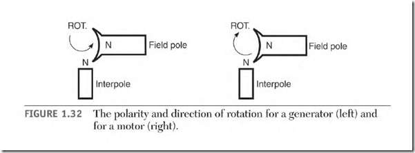
The polarity of interpoles in a generator will be the same as the field poles ahead of them (in the direction of rotation) (Fig. 1.32).
The polarity of interpoles in a motor will be the same as the field poles behind them (tn the direction of rotation) (Fig. 1.32).
There will be as many interpoles as there are field poles, or half as many. If there are half as many interpoles, each interpole coil will contain approximately twice as many turns.
Operation of Interpoles
The flux of two magnetic fields becomes distorted if they are close together. In a DC machine, the armature’s magnetic field distorts the stator field’s magnetic field. The amount of distortion varies with the change in armature load amperes. Distorted lines of force become a problem when they are forced into the neutral zone.
Armature conductors in the neutral zone are connected to commutator segments that are being switched by the brushes. The bar-to-bar voltage value should be only a portion of the line voltage. The conductors in this
ROT. ROT.
position should not cut lines of force, and there should be no voltage generated in them.
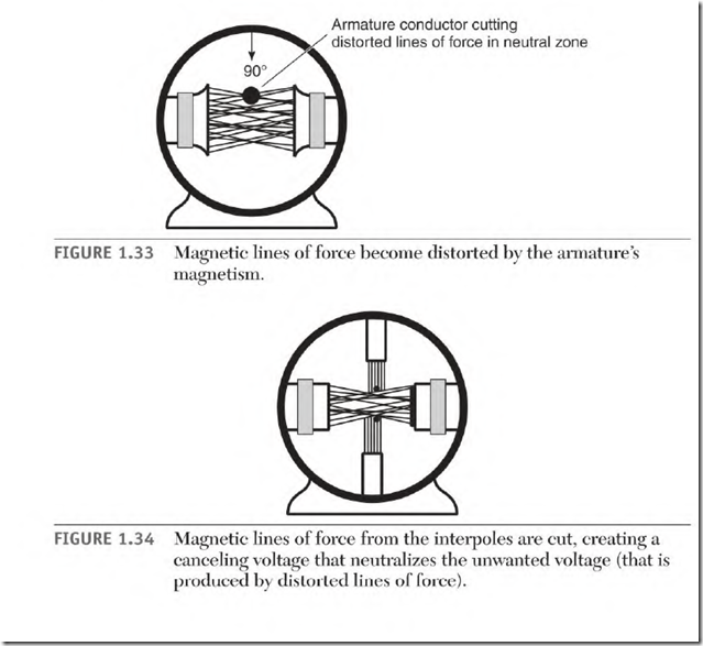
The influence of the armature’s magnetic field distorts the lines of force as shown in Fig. 1.33. Armature conductors in the neutral zone cut the distorted lines of force. This creates an unwanted voltage in the conductors. The unwanted voltage value adds to the line voltage value. The commutator’s bar-to-bar voltage now becomes too high. The result is excessive arcing at the brushes.
The brushes can be shifted to reduce the arcing, but if the load changes, arcing will again become excessive. One of the reasons brushes arc excessively is that bar-to-bar voltage is too high for the insulation to contain it.
Interpoles are located in the neutral zone. The amperes of the armature go through the interpoles. This creates magnetic lines of force in the neutral zone (Fig. 1.34). These lines of force are cut by the armature conductors
generating a voltage in them. This voltage is the opposite polarity of the unwanted voltage described above and cancels it. The result is less arcing.
The polarity of the interpoles is very important. If the polarity is wrong, the voltage generated by them will add to the unwanted voltage instead of canceling it. The bar-to-bar voltage becomes very high, resulting in extremely excessive brush arcing.
The amount of field distortion is directly related to the number of amperes in the armature circuit. With the interpoles connected in series with the armature, the number of lines of force varies with the number of armature amperes. This automatically creates the right amount of canceling voltage needed to minimize brush arcing.
Interpoles must have exactly the right number of turns of wire. If the number of turns required involves a fraction of a turn, the next higher number of turns is used. In this case, nonmagnetic shims are placed under the iron of the interpole. They fine-tune the interpole’s magnetic field to the exact strength needed.
Nonmagnetic shims are equivalent to increasing the air gap (the distance between the pole iron and the armature). Increasing the air gap weakens a pole’s strength. Use of the nonmagnetic shims allows the pole strength to be weakened and still keeps the same air gap for all interpoles.
DC motor manufacturers custom-fit the interpole iron and shims. If they are disassembled, it’s very important that the shims and pole iron be put back in their original location.

