EPO Procedure
1. Use the keyed Selector switch to energize the EPO system; the Power On pilot light will be illuminated.
2. Use the keyed 3-position Selector switch to select any of the following modes:
2.1. Armed mode
2.1.1. The Armed pilot light will be illuminated.
2.1.2. The Modbus module will be notifi ed that the system is an armed event.
2.1.3. The Mushroom buttons will be active.
2.1.4. If the keyed Selector switch fi re alarm is in the On position, the fi re alarm system can activate the system alarm.
2.1.5. If the keyed Selector switch computer interface is in the On position, the monitoring/control system can activate the system alarm using the Modbus module.
2.1.6. When one or more of the above triggers sets the alarm:
2.1.6.1. The output contacts for R7 and R8 will trip the shunt trip breakers and disconnect the power in the IT Equipment Room.
2.1.6.2. The Alarm Active pilot light will be illuminated until the timer R10 times out after 10 s, cutting off power to the shunt trip breakers.
2.1.6.3. The Critical Power Lost pilot light will be illuminated.
2.1.6.4. The Modbus module will be notifi ed of the alarm event.
2.1.6.5. The power to the panels will be cut off by the shunt trip breakers.
2.1.6.6. The EPO panel will be off.
2.1.7. When power is restored:
2.1.7.1. The system will alarm if the Reset button is not pushed within the time delay period of the R4 timer: 5 to 10 min.
2.1.7.2. The Reset button is pushed.
2.1.7.2.1. Relay R1 will reset/unlatch, and the system will return to Armed mode.
2.1.7.2.2. The Armed pilot light will be illuminated.
2.1.7.2.3. The Modbus module will be notifi ed of the reset event.
2.2. Test mode
2.2.1. The Test mode pilot light will be illuminated.
2.2.2. The R7 and R8 relays will be locked out, and the system output contacts will not close.
2.2.3. The Modbus module will be notifi ed that the panel is test mode event.
2.2.4. The Mushroom buttons will be active.
2.2.5. If the keyed Selector switch fi re alarm is in the On position, the fi re alarm system can activate the system alarm.
2.2.6. If the keyed Selector switch computer interface is in the On position, the monitoring/control system can activate the system alarm using the Modbus module.
2.2.7. When one or more of the above triggers sets the alarm:
2.2.7.1. The output contacts for R7 and R8 will not trip the shunt trip breakers and disconnect the power in the IT Equipment Room.
2.2.7.2. The Alarm Active pilot light will be illuminated until the timer R10 times out after 10 s, cutting off power to the shunt trip breakers.
2.2.7.3. The Critical Power Lost pilot light will be illuminated.
2.2.7.4. The Modbus module will be notifi ed of the alarm event.
2.2.7.5. The Test Complete pilot light will be illuminated.
2.2.8. When the test is complete:
2.2.8.1. The panel will alarm again if the Reset button is not pushed within the time delay period of the R4 timer.
2.2.8.2. The panel Reset is pushed.
2.2.8.2.1. Relay R1 will reset/unlatch, and the system will return to Armed mode.
2.2.8.2.2. The Armed pilot light will be illuminated.
2.2.8.2.3. The Modbus module will be notifi ed of the Reset event.
2.3. Maint mode
2.3.1. In Maint mode:
2.3.1.1. The system will be inactive, and all controls will be disabled.
2.3.1.2. The Maintenance Mode pilot light will be illuminated.
2.3.1.3. The Modbus module will be notifi ed of the alarm event.
Punch Press
The following is a ladder diagram for a hydraulic punch press. OSHA requires that the punch press have guards on all the openings to protect the operator when the system is running.
The press must shut down if the guards are opened. There are three modes of operation:
Hand. In Hand mode the press can be inched or jogged, which will be used in the setup of the press production run.
Off. In Off mode the press will not operate.
Auto. The Auto mode will allow the press to operate in a continuous mode.
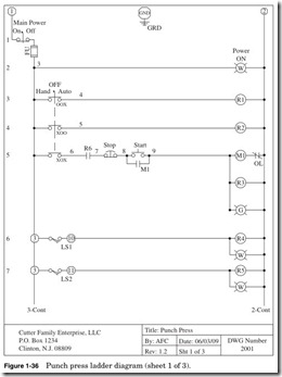
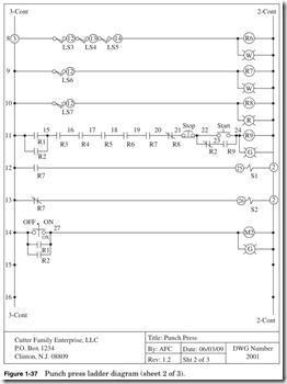
Figures 1-36 and 1-37 are sheets 1 and 2 of a three-sheet punch press ladder diagram
Shown in Fig. 1-38:
Line 1 On the left we have terminal 1, which is the hot leg, or L1, of the 120-V AC control circuit. On line 1 on the left is a key switch to turn the power on or off to the system.
The next element is the fuse. NEC 2008 Article 430-72 requires that there be overcurrent protection for control circuits. The control wiring is typically 14 gauge wire rated at 15 A (NEC 2008 Article 240.3 D-3) and is protected typically by a 10-A fuse.
The next element is the ground connection. The enclosure and the back plate of the panel must be grounded. Next we have terminal 2, which is the neutral leg, or L2, of the control circuit.
Shown in Fig. 1-39:
Line 2 The Power On indicator is a white pilot light that will be on whenever the system control power is on or energized.
Shown in Fig. 1-40:
Line 3 3-position Selector switch used to select Hand, Off, Auto. As indicated by the OOX, the Selector switch is closed in the Auto posi- tion and open in the Hand and Off positions. When closed, the relay R1 will be energized. This will close contacts in lines 11 and 14.
Shown in Fig. 1-41:
Line 4 3-position Selector switch used to select Hand, Off, Auto. As indicated by the XOO, the Selector switch is closed in the Hand posi- tion and open in the Auto and Off positions. When closed, the relay R2 will be energized. This will close contacts in lines 11 and 14.
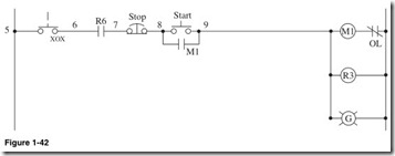
Shown in Fig. 1-42:
Line 5 3-position Selector switch used to select Hand, Off, Auto. As indicated by the XOX, the Selector switch is closed in the Hand and Auto positions and open in the Off position.
Next to the right is Normally Open contact R6. This contact will close when the motor, belt, and clutch covers are closed and will open and stop the motor if the covers are opened.
Next to the right is the Normally Closed Stop Red Mushroom push button. This button will be used to stop the motor once it is energized.
Next to the right is the Normally Open Green Start button. When closed, it will energize motor starter M1.
Next line down is the Normally Open contact of motor starter M1. When motor starter M1 is energized, this contact will close and latch.
Next to the right, motor starter M1 will be energized when the logic in line 5 is closed.
Next line down, relay R3 will be energized when motor starter M1 is energized, closing contacts in line 11.
Next line down, green pilot light G will be illuminated when motor starter M1 is energized.
Shown in Fig. 1-43:
Line 6 Terminal 3 on the terminal strip.
Next is limit switch LS1; this is closed when the front guard is closed.
Next is terminal 10 on the terminal strip.
Next to the right, relay R4 when energized will close contact in line 11.
Next line down, the white pilot light will be energized when relay R4 is energized.
Shown in Fig. 1-44:
Line 7 Terminal 3 on the terminal strip.
Next is limit switch LS2; this is closed when the rear guard is closed.
Next is terminal 11 on the terminal strip.
Next to the right, relay R5 when energized will close contact in line 11.
Next line down, white pilot light will be energized when relay R5 is energized.
Shown in Fig. 1-45:
Line 8 Terminal 3 on the terminal strip.
Next is limit switch LS3; this limit switch is closed when the cover on the motor is closed.
Next is terminal 12 on the terminal strip.
Next is limit switch LS4; this limit switch is closed when the cover on the motor belt is closed.
Next is limit switch LS5; this limit switch is closed when the cover on the clutch is closed.
Next to the right, relay R6 when energized will close contact in line 11.
Next line down, white pilot light will be energized when relay R6 is energized.
Shown in Fig. 1-46:
Line 9 Limit switch LS6 is mounted on the material feeder. The limit switch will be closed when material is in the feeder.
Next to the right, relay R7 when energized will close contact in line 11.
Next line down, white pilot light will be energized when relay R7 is energized.
Shown in Fig. 1-47:
Line 10 Limit switch LS7 is mounted on the material output bin. The limit switch will be closed when material bin is full.
Next to the right, relay R8 when energized will close contact in line 11.
Next line down, white pilot light will be energized when relay R8 is energized.
Shown in Fig. 1-48:
Line 11 Normally Open contact R1 will close when the 3-position switch is in the auto position.
Down one line, contact R2 will close when the 3-position switch is in the Hand position.
Up one line, Normally Open contact R3 will close when motor starter M1 is energized.
Next, Normally Open contact R4 will close when limit switch LS1 is closed when front guard is closed.
Next, Normally Open contact R5 will close when limit switch LS2 is closed when rear guard is closed.
Next, Normally Open contact R6 will close when limit switch LS3 is closed when motor cover is closed, LS4 when motor belt cover is closed, LS5 when the clutch cover is closed.
Next, Normally Open contact R7 will close when limit switch LS6 is closed when material feeder is closed.
Next, Normally Closed contact R8 will close when limit switch LS7 is closed when material output bin is full.
Next, Normally Closed Red Mushroom push button will unlatch relay R9.
Down one line, Normally Closed contact R2 will open when the 3-position select switch is in the Off or Hand positions. This will allow the press to be jogged or inched in the Hand mode.
Next, Normally Open contact R9 will close and latch the relay R9 when the Start push button is closed.
Up one line, Normally Open green Start push button will energize when the push button is pressed and the logic in line 11 is closed.
Next, relay R9 will energize when the logic in line 11 is closed or true.
One line down, green pilot light will illuminate when relay R9 is energized.
Shown in Fig. 1-49:
Line 12 Normally Open contact R9 will close when relay R9 line 11 is energized.
Next, terminal 25 on the terminal strip.
Next, solenoid S1 will be energized, which will close the clutch.
Shown in Fig. 1-50:
Line 13 Normally Closed contact R9 will open when relay R9 line 11 is energized.
Next, terminal 25 on the terminal strip.
Next, solenoid S2 will be deenergized, which will open the brake.
Shown in Fig. 1-51:
Line 14 2-position switch is closed in the On position and open in the Off position. When in the On position, this will energize motor starter M2 and run the press oiler.
Down one line, Normally Open contact R1 will close when the 3-position Selector switch is in the Auto position; this will energize motor starter M2 and run the press oiler.
Down one line, Normally Open contact R2 will close when the 3-position Selector switch is in the Hand position; this will energize motor starter M2 and run the press oiler.
Next, motor starter M2 when energized will run the press oiler.
Down one line, green pilot light will be illuminated when motor starter M2 is energized.
Punch Press Procedure
1. Use the keyed Selector switch to energize the punch press system; the Power On pilot light will be illuminated.
2. Use the keyed three-position Selector switch to select any of the following modes:
2.1. Hand mode
2.1.1. The motor can be started by pressing the Start button in line 5.
2.1.2. Limit switch LS1 will energize relay R4 and white pilot light when front guard is closed.
1.1.1. Limit switch LS2 will energize relay R5 and white pilot light when rear guard is closed.
1.1.2. Limit switches LS3 motor cover, LS4 motor belt cover, and LS5 clutch cover are closed. This will energize relay R6 and white pilot light.
1.1.3. Limit switch LS6 will energize relay R7 and white pilot light when material is in the feeder.
1.1.4. Limit switch LS7 will energize relay R8 and white pilot light when material bin is full.
1.1.5. If all the logic in line 11 is closed, then the punch press will operate in the jog or inch mode.
1.1.6. Motor starter M2 will be energized and run the oiler.
1.2. Off mode
1.2.1. The motor cannot be started.
1.2.2. Limit switch LS1 will energize relay R4 and white pilot light when front guard is closed.
1.2.3. Limit switch LS2 will energize relay R5 and white pilot light when rear guard is closed.
1.2.4. Limit switches LS3 motor cover, LS4 motor belt cover, and LS5 clutch cover are closed. This will energize relay R6 and white pilot light.
1.2.5. Limit switch LS6 will energize relay R7 and white pilot light when material is in the feeder.
1.2.6. Limit switch LS7 will energize relay R8 and white pilot light when material bin is full.
1.2.7. In line 11 Normally Open contacts R1 and R2 will be opened, and the punch press will not operate.
1.2.8. Motor starter M2 will be energized and run the oiler if the 2-position Selector switch is in the On position.
1.3. Auto mode
1.3.1. The motor can be started by pressing the Start button in line 5 if the logic in line is true.
1.3.2. Limit switch LS1 will energize relay R4 and white pilot light when front guard is closed.
1.3.3. Limit switch LS2 will energize relay R5 and white pilot light when rear guard is closed.
1.3.4. Limit switches LS3 motor cover, LS4 motor belt cover, and LS5 clutch cover are closed. This will energize relay R6 and white pilot light.
1.3.5. Limit switch LS6 will energize relay R7 and white pilot light when material is in the feeder.
1.3.6. Limit switch LS7 will energize relay R8 and white pilot light when material bin is full.
1.1.1. If all the logic in line 11 is closed, then the punch press will operate in the Run mode.
1.1.2. Motor starter M2 will be energized and run the oiler.
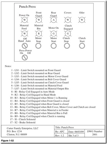
Shown in Fig. 1-52:
Front panel display and notes. This is useful to locate the devices on the panel and the functions of the system devices.


